Korean Translation · 원문·번역 대역
UN GTR 21 (DEVP) — 원문·번역 대역
영문 원문 ↔ 한글 번역을 문단별로 좌우 나란히, 원문 그림 포함. ECE/TRANS/180/Add.21.
📄 원문(UNECE) 열기 ↗ECE/TRANS/180/Add.21
한글은 업로드된 번역본, 원문은 영문 GTR 21. 서술형 본문은 자동 복원·정렬, 정의·규정 본문·부속서는 직접 매칭해 채웠습니다. 번호 없는 연속 문단은 상위 조항에 합쳤습니다. 그림은 원문에서 추출해 본문 위치에 삽입했습니다.
문단
원문 (English)
번역 (한글)
—
문서: ECE/TRANS/180/Add.21 (2021년 1월 18일) · Global Registry 등재 2020년 11월 11일 제목: 하이브리드 전기차 및 2개 이상의 전기기계를 구동에 사용하는 순수 전기차의 시스템 출력 결정에 관한 UN 글로벌 기술 규정 — 전동화 차량 출력 결정(Determination of Electrified Vehicle Power, DEVP)
번역 메모: 조항·문단 번호, 수식, 표, 그림 번호를 원문 그대로 유지했습니다. 그림 자체(파워트레인 도식 등)는 원문 PDF를 참조하십시오. 정의된 용어는 처음 또는 핵심 위치에서 한국어(영문)을 병기했습니다. 본 번역은 내용 파악용이며, 공식 인용 시 원문(ECE/TRANS/180/Add.21)을 확인하십시오.
번역 메모: 조항·문단 번호, 수식, 표, 그림 번호를 원문 그대로 유지했습니다. 그림 자체(파워트레인 도식 등)는 원문 PDF를 참조하십시오. 정의된 용어는 처음 또는 핵심 위치에서 한국어(영문)을 병기했습니다. 본 번역은 내용 파악용이며, 공식 인용 시 원문(ECE/TRANS/180/Add.21)을 확인하십시오.
목차
—
I. 기술적 근거 및 정당성 기술 (Statement of technical rationale and justification) - A. 서론 - B. 기술적 배경 - C. 기술적 근거 및 정당성 - D. 기술적 실행가능성, 예상 비용 및 편익
II. 규정 본문 (Text of the GTR) - 1. 목적 - 2. 적용 범위 - 3. 정의 - 4. 약어 - 5. 시험 조건 - 6. 시험 절차
부속서 - 부속서 1: 출력 결정 기준점의 식별 - 부속서 2: 최대출력 속도의 결정 - 부속서 3: [유보] 방법 동등성의 결정
II. 규정 본문 (Text of the GTR) - 1. 목적 - 2. 적용 범위 - 3. 정의 - 4. 약어 - 5. 시험 조건 - 6. 시험 절차
부속서 - 부속서 1: 출력 결정 기준점의 식별 - 부속서 2: 최대출력 속도의 결정 - 부속서 3: [유보] 방법 동등성의 결정
I. 기술적 근거 및 정당성 기술
A. 서론
1
1. Passenger vehicles are commonly assigned a vehicle power rating, which is useful for comparing the performance of different vehicles. Vehicle power rating has also been used for other purposes such as vehicle classification, customer information, insurance, and taxation.
1. 승용차에는 일반적으로 차량 출력 정격(power rating)이 부여되며, 이는 서로 다른 차량의 성능을 비교하는 데 유용하다. 차량 출력 정격은 차량 분류, 소비자 정보 제공, 보험, 과세 등 다른 목적으로도 사용되어 왔다.
2
2. Historically, almost every passenger vehicle produced for the consumer market has been powered exclusively by an internal combustion engine (ICE). The vehicle power rating assigned to these conventional vehicles has customarily been the same as the rated power of the engine, as determined by an engine bench test. This is a convenient way to assign a power rating to a vehicle, because the engine power rating may then be applied to any vehicle that uses the same engine.
2. 역사적으로 소비자 시장용으로 생산된 거의 모든 승용차는 내연기관(ICE) 단독으로 구동되어 왔다. 이러한 종래 차량에 부여되는 차량 출력 정격은 관례적으로 엔진 벤치 시험으로 측정한 엔진의 정격출력과 동일하게 정해졌다. 이는 차량에 출력 정격을 부여하는 편리한 방법인데, 동일한 엔진을 사용하는 모든 차량에 그 엔진 출력 정격을 그대로 적용할 수 있기 때문이다.
3
3. As a measure of real-world vehicle performance, this traditional measure is imperfect, since it does not account for the power lost in the drivetrain between the engine and the road. However, it has become well established and is generally accepted as a useful metric, in part because conventional vehicles have only one engine, and its full rated power is typically available for propulsion.
3. 다만 실제 도로 성능의 척도로서 이 전통적 측정값은 불완전하다. 엔진과 노면 사이의 구동계에서 손실되는 출력을 반영하지 못하기 때문이다. 그럼에도 이 방식은 잘 확립되어 유용한 지표로 널리 받아들여져 왔는데, 이는 부분적으로 종래 차량이 엔진을 하나만 가지며 그 전체 정격출력이 일반적으로 구동에 사용 가능하기 때문이다.
4
4. Today, electrified vehicles such as hybrid electric vehicles (HEVs) and pure electric vehicles (PEVs) with multiple drive motors represent an increasing share of the market. A vehicle power rating is not as easy to assign to these vehicles because they combine more than one propulsion source, such as an engine and an electric machine, or multiple electric machines.
4. 오늘날 다수의 구동 모터를 가진 하이브리드 전기차(HEV)와 순수 전기차(PEV) 같은 전동화 차량의 시장 점유율이 커지고 있다. 이러한 차량에는 출력 정격을 부여하기가 쉽지 않은데, 엔진과 전기기계, 또는 복수의 전기기계처럼 둘 이상의 추진원을 결합하기 때문이다.
5
5. For these vehicles, the available power depends on how the control system combines the power of each propulsion source when the driver demands maximum power. While it may seem that this would simply be the sum of the rated power of each component, this is not necessarily valid in practice. It will result in an overestimate if, for example, the electric machine is limited by the available battery power, or if the control system limits or reassigns some of the nominal capacity, such as to maintain traction or charge the battery.
5. 이러한 차량의 가용 출력은 운전자가 최대출력을 요구할 때 제어 시스템이 각 추진원의 출력을 어떻게 결합하는지에 달려 있다. 단순히 각 구성요소 정격출력의 합이라고 보일 수 있으나, 실제로는 반드시 그렇지 않다. 예를 들어 전기기계가 가용 배터리 전력에 의해 제한되거나, 제어 시스템이 견인력 유지나 배터리 충전을 위해 공칭 용량의 일부를 제한·재배분하는 경우, 단순 합산은 과대평가를 낳는다.
6
6. Owing to the pressing need to reduce emissions of greenhouse gases (GHG) and other air pollutants, the market share of electrified vehicles is expected to grow in the future. This intensifies the need for a standard method for assigning a vehicle power rating to electrified vehicles.
6. 온실가스(GHG)와 기타 대기오염물질 배출 저감의 시급한 필요성으로 인해 전동화 차량의 시장 점유율은 앞으로 더 커질 것으로 예상된다. 이는 전동화 차량에 차량 출력 정격을 부여하는 표준 방법의 필요성을 더욱 강화한다.
7
7. Electrified vehicles and conventional vehicles are likely to coexist in the market for some time. Many existing regulations and procedures, such as WLTP, apply to both conventional and electrified vehicles, and require a power rating as an input. In order to be used equitably for such purposes, a power rating for electrified vehicles should be qualitatively and quantitatively comparable with the traditional engine-based power ratings of conventional vehicles. B. Technical background
7. 전동화 차량과 종래 차량은 상당 기간 시장에서 공존할 가능성이 높다. WLTP를 비롯한 많은 기존 규정·절차가 종래 차량과 전동화 차량 모두에 적용되며 출력 정격을 입력값으로 요구한다. 이러한 목적에 공평하게 사용되려면, 전동화 차량의 출력 정격은 종래 차량의 전통적 엔진 기반 출력 정격과 질적·양적으로 비교 가능해야 한다.
B. 기술적 배경
1. 주요 기술적 과제
8
8. Developing a test procedure and system power rating that fits the requirements presents two primary technical challenges: (a) The first challenge is to identify a reliable and repeatable way to command a vehicle to deliver maximum power in a laboratory setting. (b) The second challenge is to identify a comparable and valid basis for the system power rating and to identify the measurements and calculations necessary to produce it. (a) Commanding maximum power
8. 요건에 부합하는 시험 절차와 시스템 출력 정격을 개발하는 데에는 두 가지 주요 기술적 과제가 있다. - (a) 첫째 과제는 실험실 환경에서 차량이 최대출력을 내도록 지령하는 신뢰성 있고 재현 가능한 방법을 찾는 것이다. - (b) 둘째 과제는 시스템 출력 정격의 비교 가능하고 타당한 기준을 찾고, 이를 산출하는 데 필요한 측정과 계산을 식별하는 것이다.
(a) 최대출력 지령
9
9. As part of their standards development efforts, SAE and ISO studied ways to elicit maximum power in a laboratory setting (more details about the Informal Working Group (IWG) on Electric Vehicle and the Environment (EVE), SAE and ISO activities related to the topic of power measurement of electrified powertrain can be found in the technical report of this UN GTR). This resulted in identification of a reliable and repeatable method to do this by use of the fixed-speed setting of a chassis dynamometer. The condition of maximum power is determined by driving the vehicle on the dynamometer at a series of fixed dynamometer speeds to find the maximum brake power of the dynamometer that the vehicle is able to run against. At each speed, the accelerator is rapidly and fully depressed for at least 10 seconds. The speed at which the dynamometer records the highest power is recorded. The system power is then determined at this fixed dynamometer speed. (b) Basis and measurements
9. 표준 개발 노력의 일환으로 SAE와 ISO는 실험실 환경에서 최대출력을 끌어내는 방법을 연구하였다(EVE 비공식작업반(IWG), SAE, ISO의 전동화 파워트레인 출력 측정 관련 활동에 대한 상세 내용은 본 UN GTR의 기술보고서 참조). 그 결과, 섀시 동력계의 고정속도 설정을 이용하는 신뢰성 있고 재현 가능한 방법이 도출되었다. 최대출력 조건은, 차량을 동력계에서 일련의 고정 동력계 속도로 주행시켜 차량이 견뎌낼 수 있는 동력계 최대 제동출력을 찾음으로써 결정된다. 각 속도에서 가속페달을 신속하게 끝까지 최소 10초간 밟는다. 동력계가 최고 출력을 기록한 속도를 기록한다. 그런 다음 이 고정 동력계 속도에서 시스템 출력을 결정한다.
(b) 기준과 측정
10
10. In early discussions, the IWG on EVE discussed a number of conceptually simple measurement bases for electrified vehicle power.
10. 초기 논의에서 EVE IWG는 전동화 차량 출력에 대한 개념적으로 단순한 여러 측정 기준을 검토하였다.
11
11. One very simple basis would simply measure the peak power delivered to the wheels. This would be compatible with all electrified vehicles regardless of their powertrain architecture. If also extended to conventional vehicles, it would rate all vehicles on a directly comparable basis, and would represent real-world power more effectively than the traditional measure because it includes the effect of losses in the drivetrain. However, for the same reason, this would result in power ratings that are not comparable to the traditional measure, which continues to be used in many applications.
11. 매우 단순한 한 기준은 단지 바퀴에 전달되는 피크 출력을 측정하는 것이다. 이는 파워트레인 구조와 무관하게 모든 전동화 차량에 적용 가능하다. 종래 차량에까지 확장하면 모든 차량을 직접 비교 가능한 기준으로 평가하게 되며, 구동계 손실을 포함하므로 전통적 측정값보다 실제 도로 출력을 더 잘 나타낸다. 그러나 같은 이유로, 이 값은 여전히 많은 용도에서 쓰이는 전통적 측정값과는 비교 불가능한 출력 정격을 낳는다.
12
12. Another simple approach would measure the peak power delivered to the wheels and then adjust it by an assumed transmission efficiency. This approach recognizes that an engine-based power rating, in theory, should be identical to the peak power delivered to the wheels divided by the mechanical conversion efficiency of the drivetrain (e.g. gearbox or transmission). By extension, a highly comparable power rating for an electrified vehicle could be determined by measuring the peak power delivered to the wheels and dividing by a typical (conventional) drivetrain efficiency at peak load, perhaps 90 to 95 percent. However, it was not clear that this approach would represent all hybrid powertrains equally, nor that a single assumed drivetrain efficiency would represent all comparison vehicles equally.
12. 또 다른 단순한 접근은 바퀴 전달 피크 출력을 측정한 뒤 가정한 변속기 효율로 보정하는 것이다. 이는 엔진 기반 출력 정격이 이론상 바퀴 전달 피크 출력을 구동계(기어박스·변속기)의 기계적 변환 효율로 나눈 값과 같아야 한다는 점에 착안한 것이다. 이를 확장하면, 바퀴 전달 피크 출력을 측정하여 전형적(종래) 구동계의 최대부하 효율(대략 90~95%)로 나눔으로써 전동화 차량에 매우 비교 가능한 출력 정격을 부여할 수 있다. 그러나 이 방식이 모든 하이브리드 파워트레인을 동등하게 대표하는지, 또 단일하게 가정한 구동계 효율이 모든 비교 대상 차량을 동등하게 대표하는지는 불분명하였다.
13
13. Another possibility would sum the power of the engine with the measured power output of the battery. Many hybrid vehicles operate the engine at full throttle when the driver demands maximum power, meaning that engine power can be estimated from engine speed by reference to a full load power curve. Battery power is also reasonably simple to measure, and measuring at the battery avoids the need to instrument individual inverters or motors. However, it would neglect electrical conversion losses in the latter, and so might tend to produce optimistic results for highly electrified powertrains.
13. 또 다른 가능성은 엔진 출력과 배터리의 측정 출력을 합산하는 것이다. 많은 하이브리드 차량은 운전자가 최대출력을 요구할 때 엔진을 전부하(full throttle)로 운전하므로, 엔진 출력을 전부하 출력곡선을 참조해 엔진 회전수로부터 추정할 수 있다. 배터리 출력 또한 비교적 간단히 측정할 수 있으며, 배터리에서 측정하면 개별 인버터나 모터를 계측할 필요가 없다. 그러나 이는 후자의 전기 변환 손실을 무시하므로, 고도로 전동화된 파워트레인에서는 낙관적인 결과를 낳는 경향이 있다.
14
14. Recognizing that these relatively simple methods vary in their comparability and fairness, the IWG on EVE sought to identify a more sophisticated approach.
14. 이처럼 비교적 단순한 방법들이 비교 가능성과 공정성 면에서 차이가 있음을 인식하고, EVE IWG는 보다 정교한 접근을 모색하였다.
15
15. Conceptually, a comparable and fair rating would be based on the power that passes through the powertrain at a point that is mechanically analogous to the output shaft of a conventional engine (as opposed to the wheels or the battery, where the losses would be different). Intuitively, this point would include the mechanical output shafts of any propulsion energy converters (i.e. engine and electric machines) that contribute propulsion energy when the driver commands maximum power.
15. 개념적으로, 비교 가능하고 공정한 정격은 종래 엔진의 출력축에 기계적으로 가장 가까운 지점(바퀴나 배터리가 아닌, 손실이 달라지는 지점)을 통과하는 출력에 기반해야 한다. 직관적으로 이 지점은, 운전자가 최대출력을 지령할 때 추진 에너지를 기여하는 모든 추진 에너지 변환장치(즉 엔진과 전기기계)의 기계적 출력축을 포함한다.
16
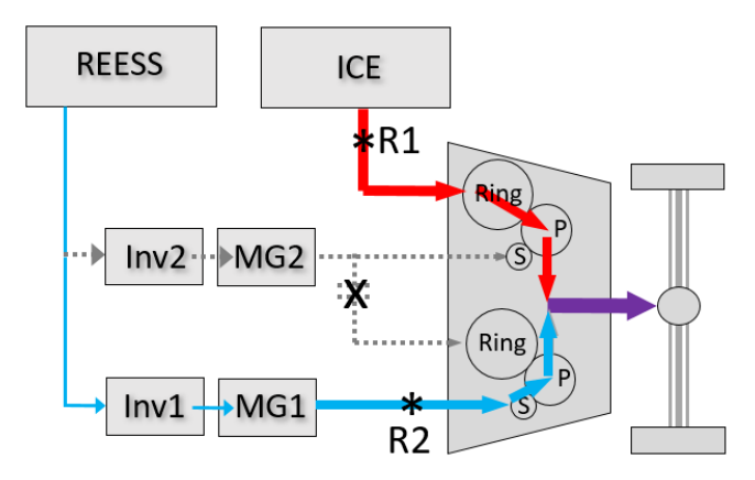
16. As an example, Figure 1 illustrates a typical P2 hybrid configuration, in which ICE power and electric motor power is mechanically combined on a single shaft. It identifies two "reference points," R1 and R2, which together are mechanically analogous to the power output of the engine in a conventional vehicle. That is, they represent where the mechanical power that drives the wheels is first produced from stored energy. The goal would be to determine the sum of the mechanical power passing through R1 and R2 when the vehicle is producing maximum power. Figure 1 Example of reference points for system power determination
16. 예로서, [그림 1]은 ICE 출력과 전동 모터 출력이 단일 축에서 기계적으로 결합되는 전형적 P2 하이브리드 구성을 보여준다. 여기에 두 개의 “기준점(reference point)” R1과 R2가 식별되며, 이 둘은 함께 종래 차량 엔진의 출력에 기계적으로 대응한다. 즉, 바퀴를 구동하는 기계적 출력이 저장된 에너지로부터 처음 생성되는 지점을 나타낸다. 목표는 차량이 최대출력을 낼 때 R1과 R2를 통과하는 기계적 출력의 합을 결정하는 것이다.

—
그림 1. 시스템 출력 결정을 위한 기준점 예시 — REESS–Inv–EM(R2)와 ICE(R1)가 단일 축에 결합
17
17. In theory, the most direct approach to measure the power at R1 and R2 would be to instrument the corresponding shafts with torque and speed meters. However, this requires invasive instrumentation, may not be possible in some cases, and is unlikely to be practical in a type approval context.
17. 이론상 R1, R2의 출력을 측정하는 가장 직접적인 방법은 해당 축에 토크·속도계를 설치하는 것이다. 그러나 이는 침습적 계측이 필요하고, 경우에 따라 불가능하며, 형식승인 맥락에서는 실용적이지 않다.
18
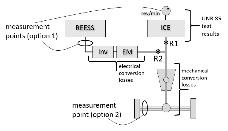
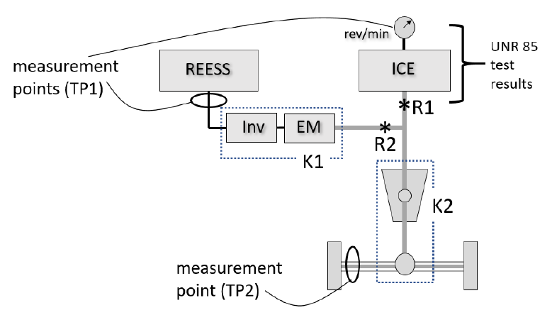
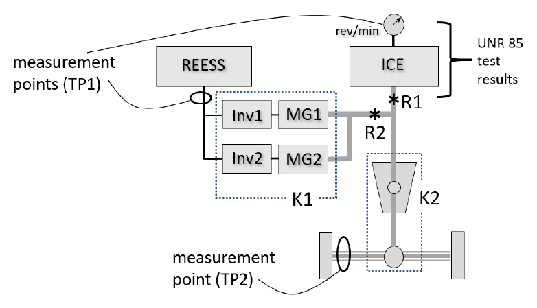
18. A more practical approach would measure power flow at other points in the powertrain that are easier to instrument, and estimate the power at reference points R1 and R2 by accounting for the losses between the measuring points and the reference points. As shown in Figure 2, the measuring points could either be upstream or downstream of the reference points. An option for measuring upstream (option 1) might include measuring engine speed and converting it to the mechanical power output at R1, and measuring REESS power output and converting it to the power at R2 by accounting for electrical conversion losses. Options for measuring downstream (option 2) might include measuring the power delivered to the axle by means of wheel torque and speed sensors or a hub dynamometer, and then determining the sum of R1 and R2 by accounting for mechanical conversion losses in the drivetrain. Figure 2 Possible measurement points to estimate power at R1 and R2 for parallel P2 hybrid Note: measurement point for option 2 represents both axle shafts.
18. 보다 실용적인 접근은 계측이 더 쉬운 다른 지점에서 동력 흐름을 측정하고, 측정점과 기준점 사이의 손실을 보정하여 R1, R2의 출력을 추정하는 것이다. [그림 2]에서 보듯 측정점은 기준점의 상류 또는 하류일 수 있다. 상류 측정(옵션 1)은 엔진 회전수를 측정해 R1의 기계적 출력으로 변환하고, REESS 출력을 측정해 전기 변환 손실을 보정함으로써 R2의 출력으로 변환하는 방식을 포함할 수 있다. 하류 측정(옵션 2)은 휠 토크·속도 센서나 허브 동력계로 차축 전달 출력을 측정한 뒤 구동계의 기계적 변환 손실을 보정하여 R1+R2의 합을 구하는 방식을 포함할 수 있다.
—
그림 2. 병렬 P2 하이브리드에서 R1·R2 출력 추정을 위한 측정점 — 옵션1(상류: REESS·엔진), 옵션2(하류: 차축). 옵션2 측정점은 양쪽 차축을 대표
19
19. Electrified powertrains vary widely, and can include power flow paths that are much more complex than those depicted here. However, once the reference points are identified, it should be possible to estimate the power at the reference points by taking appropriate measurements when the vehicle is generating maximum power, and accounting for the losses between the measurement points and the reference points using component test data or sound engineering judgement.
19. 전동화 파워트레인은 매우 다양하며, 여기 묘사된 것보다 훨씬 복잡한 동력 흐름 경로를 가질 수 있다. 그러나 일단 기준점이 식별되면, 차량이 최대출력을 낼 때 적절한 측정을 수행하고 측정점과 기준점 사이 손실을 구성품 시험 데이터나 건전한 공학적 판단으로 보정함으로써 기준점 출력을 추정할 수 있어야 한다.
2. 정확도와 정밀도
20
20. It should be noted that the traditional engine-based metric does not perfectly represent the road power available to the driver, because it neglects losses in the transmission. This also makes it imprecise, in that the road power may vary significantly from one vehicle model to another due to differences in drivetrain losses.
20. 전통적 엔진 기반 지표는 변속기 손실을 무시하므로 운전자가 쓸 수 있는 도로 출력을 완벽히 나타내지 못한다는 점에 유의해야 한다. 또한 구동계 손실 차이로 인해 도로 출력이 차종마다 크게 달라질 수 있어 정밀도도 떨어진다.
21
21. Engine power ratings are also somewhat imprecise. For example, UN Regulation No. 85 allows the declared power value for a production engine to vary by ± 2 percent from the certification test result, and by ± 5 percent for conformity of production.
21. 엔진 출력 정격 자체도 다소 부정확하다. 예를 들어 UN 규정 제85호는 양산 엔진의 신고 출력값이 인증 시험 결과로부터 ±2%, 생산 적합성(COP)에 대해서는 ±5% 변동하는 것을 허용한다.
22
22. A system power metric for electrified vehicles might therefore be held to a similar level of accuracy and precision.
22. 따라서 전동화 차량의 시스템 출력 지표도 이와 유사한 수준의 정확도·정밀도로 다루어질 수 있다.
3. 타 기관의 작업
23
23. The IWG on EVE received presentations from experts with several organizations that were studying the problem of hybrid system power determination. (a) SAE J2908
23. EVE IWG는 하이브리드 시스템 출력 결정 문제를 연구하던 여러 기관 전문가들의 발표를 청취하였다.
(a) SAE J2908
24
24. The SAE J2908 Task Force led by Argonne National Laboratory (ANL) started its project in November 2014. Three primary methods of determining HEV system power were initially investigated (referred to here as Method 1, Method 2, and Method 3).
24. 아르곤 국립연구소(ANL)가 주도한 SAE J2908 태스크포스는 2014년 11월에 프로젝트를 시작하였다. HEV 시스템 출력 결정의 세 가지 주요 방법(여기서 Method 1, 2, 3로 칭함)이 초기에 검토되었다.
25
25. SAE Method 1 was the sum of engine power (estimated from bench test results) and measured DC power from the battery (neglecting electrical conversion losses in the inverter and electric machines). SAE Method 2 was the sum of estimated shaft powers from the engine and the electric machines (determined from bench test results and onboard data, respectively). SAE Method 3 was the measured power at the axle or wheel.
25. SAE Method 1은 엔진 출력(벤치 시험 결과로 추정)과 배터리의 측정 DC 출력의 합(인버터·전기기계의 전기 변환 손실 무시)이었다. SAE Method 2는 엔진과 전기기계의 추정 축출력의 합(각각 벤치 시험 결과와 온보드 데이터로 결정)이었다. SAE Method 3은 차축 또는 바퀴에서의 측정 출력이었다.
26
26. The IWG on EVE agreed with the characterization of these three primary methods as reasonable approaches to measure system power. However, the three methods varied in terms of how well the measure could be compared to the traditional power ratings for conventional vehicles, and in terms of the ability to verify a reported value. Method 1 was conceptually similar to the conventional engine-based rating and would be straightforward to verify by measurement, but neglected some losses. Method 2 was most comparable to the conventional rating, but would impose the highest burden of instrumentation to verify. Method 3 would be easily verifiable by dynamometer testing, but because a wheel power measurement accounts for losses in the drivetrain, it would not be as comparable to the conventional rating, which does not. (b) KATRI standard
26. EVE IWG는 이 세 가지 주요 방법이 시스템 출력 측정의 합리적 접근이라는 평가에 동의하였다. 다만 세 방법은 종래 차량의 전통적 출력 정격과의 비교 가능성, 그리고 보고값의 검증 가능성 면에서 차이가 있었다. Method 1은 전통적 엔진 기반 정격과 개념적으로 유사하고 측정으로 검증하기 쉬우나 일부 손실을 무시한다. Method 2는 전통적 정격과 가장 비교 가능하나 검증을 위한 계측 부담이 가장 크다. Method 3은 동력계 시험으로 쉽게 검증되나, 바퀴 출력 측정이 구동계 손실을 포함하므로 그렇지 않은 전통적 정격과는 비교 가능성이 떨어진다.
(b) KATRI 표준
27
27. KATRI started a research project in July 2013 with the aim of developing a national standard for the determination of a representative power for (Non) Off-Vehicle Charge ((N)OVC)-HEVs and PEVs with in-wheel motors. It was completed in June 2015. Nominal rating and system power tests were studied using a powertrain dynamometer or a chassis dynamometer with added instrumentation. The definition of hybrid system power follows the same approach as SAE Method 1, namely that it involves a simple addition of the rated engine power and the electric power of the battery. The engine power is the rated power according to UN Regulation No.
27. KATRI(한국 자동차안전연구원)는 2013년 7월, 인휠 모터를 가진 (비)외부충전식((N)OVC) HEV 및 PEV의 대표 출력 결정을 위한 국가 표준 개발을 목표로 연구 프로젝트를 시작하여 2015년 6월에 완료하였다. 파워트레인 동력계 또는 계측을 추가한 섀시 동력계를 사용하여 공칭 정격과 시스템 출력 시험을 연구하였다. 하이브리드 시스템 출력의 정의는 SAE Method 1과 동일한 접근, 즉 엔진 정격출력과 배터리 전기출력의 단순 합산을 따른다. 엔진 출력은 UN 규정 제85호에 따른 정격출력이다. 전기출력은 완충된 REESS의 측정 출력으로, 섀시 동력계 시험으로 결정된다. SAE 방법론과 비교하여, 바퀴·차축 출력의 정확한 측정뿐 아니라 시스템 토크까지 제공하는 다소 더 정교한 시험이다.
(c) ISO 20762
28
28. ISO conducted a project under New Work Item Proposal (NWIP) N3477 proposed by the Japan Automobile Research Institute (JARI), approved in June 2015. It started as a formal project of ISO/ TC22/SC37/WG02 and was finalized as ISO Standard 20762 in 2018.
28. ISO는 일본자동차연구소(JARI)가 제안하여 2015년 6월에 승인된 신규작업항목제안(NWIP) N3477에 따라 프로젝트를 수행하였다. ISO/TC22/SC37/WG02의 공식 프로젝트로 시작되어 2018년 ISO 표준 20762로 확정되었다.
29
29. The ISO method includes two alternative test procedures, referred to as test procedure 1 (TP1) and test procedure 2 (TP2). Note: measurement point for TP2 represents both axle shafts.
29. ISO 방법은 두 가지 대체 시험 절차, 즉 시험 절차 1(TP1)과 시험 절차 2(TP2)를 포함한다.
30
—
30. [그림 3]에서 보듯 TP1은 엔진과 REESS에서의 상류 측정에 기반하고, TP2는 휠 허브 또는 차축에서의 하류 측정에 기반한다.

—
그림 3. ISO 시험 절차 TP1·TP2의 측정점. TP2 측정점은 양쪽 차축을 대표
31
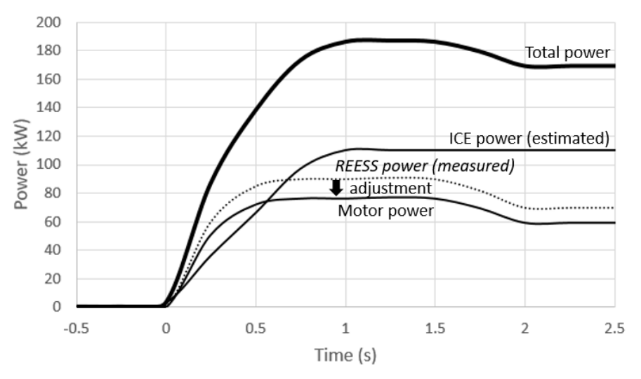
31. TP1 is similar to SAE Method 1, but additionally accounts for electrical conversion losses. Total power is the sum of estimated engine power and estimated motor power. Engine power is the rated power by ISO 1585 (or UN Regulation No. 85) at the observed operating point. Motor power is based on measured REESS power, adjusted by a factor (known as K, with a default value of 0.85) that represents combined efficiency of the inverter(s) and electric machine(s). (Electrical power to the accessories is also estimated or measured and deducted from the REESS power.) Figure 4 illustrates how total power is modelled under TP1. Figure 4 TP1 as sum of estimated engine power and estimated motor power
31. TP1은 SAE Method 1과 유사하나 추가로 전기 변환 손실을 반영한다. 총출력은 추정 엔진 출력과 추정 모터 출력의 합이다. 엔진 출력은 관측된 운전점에서 ISO 1585(또는 UN 규정 제85호)에 따른 정격출력이다. 모터 출력은 측정된 REESS 출력에, 인버터(들)와 전기기계(들)의 결합 효율을 나타내는 계수(K, 기본값 0.85)를 곱하여 보정한 값에 기반한다. (보조장치로 가는 전기출력도 추정 또는 측정하여 REESS 출력에서 차감한다.) [그림 4]는 TP1에서 총출력을 모델링하는 방식을 보여준다.
—
그림 4. 추정 엔진 출력 + 추정 모터 출력의 합으로서의 TP1 — 시간에 따른 총출력·ICE 출력(추정)·REESS 출력(측정)·보정 후 모터 출력 곡선
32
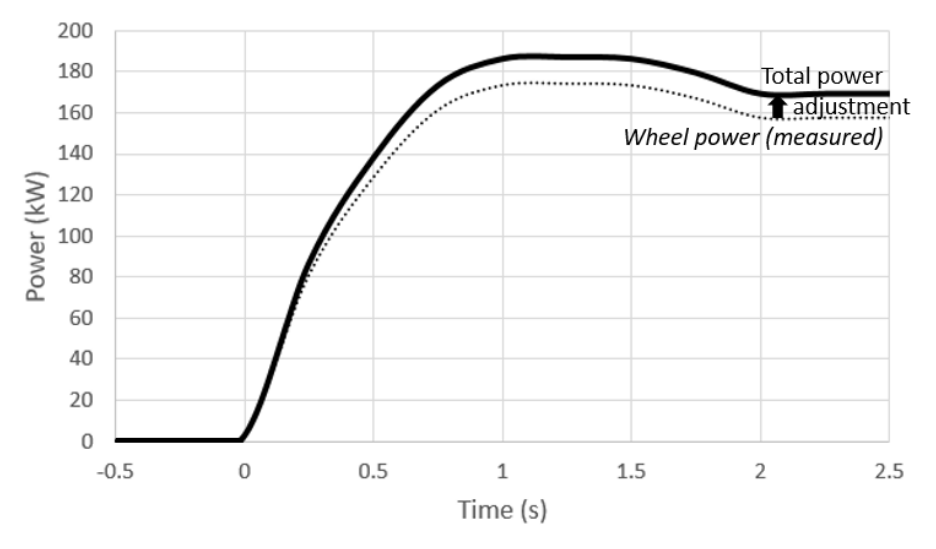
32. TP2 is similar to SAE Method
32. TP2는 SAE Method 3과 유사하다. 총출력은 바퀴 또는 차축에서 측정한 출력에, 기어박스 손실을 나타내는 계수(ηgb)로 보정한 값이다. 여러 하이브리드 구동계에 대한 ηgb 기본값이 제공된다. [그림 5]는 TP2에서 총출력을 모델링하는 방식을 보여준다.
—
그림 5. 기어박스 손실 보정 후 측정 휠 출력으로서의 TP2
33
33. It could be said that TP1 and TP2 provide the flexibility in measurement options provided by SAE Method 1 and 3, while the inclusion of the adjustment factors K and ηgb result in a metric more like that of SAE Method 2, which is most comparable to the traditional measure.
33. TP1과 TP2는 SAE Method 1·3이 제공하는 측정 옵션의 유연성을 제공하면서도, 보정계수 K와 ηgb를 포함함으로써 전통적 측정값과 가장 비교 가능한 SAE Method 2에 더 가까운 지표를 만든다고 할 수 있다.
34
34. In both TP1 and TP2, power is measured when the hybrid system as a whole delivers maximum power on a dynamometer running at a fixed speed. If not provided by the manufacturer, the fixed speed at which maximum power is delivered is determined by carrying out a series of test runs while driving the vehicle on the dynamometer at a series of fixed speeds to find the maximum brake power of the dynamometer that the vehicle is able to run against. At each speed, the accelerator is rapidly and fully depressed for at least 10 seconds.
34. TP1과 TP2 모두, 하이브리드 시스템 전체가 고정속도로 운전되는 동력계에서 최대출력을 낼 때 출력을 측정한다. 제조사가 제공하지 않은 경우, 최대출력이 나오는 고정속도는 일련의 고정속도로 차량을 주행시켜 차량이 견뎌낼 수 있는 동력계 최대 제동출력을 찾는 일련의 시험 주행으로 결정한다. 각 속도에서 가속페달을 신속하게 끝까지 최소 10초간 밟는다.
35
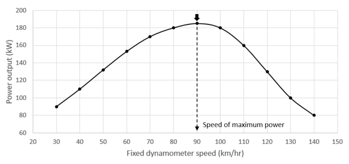
35. As shown in Figure 6, the tests result in a power-versus-speed curve that helps to identify the fixed dynamometer speed at which maximum power is generated. If necessary, the evaluation is continued with smaller speed steps near the peak of the curve until the speed of the peak power is accurately identified. The power test is then performed at this fixed speed. Figure 6 Identification of speed of maximum vehicle power
35. [그림 6]에서 보듯, 이 시험들은 최대출력이 발생하는 고정 동력계 속도를 식별하는 데 도움이 되는 출력-속도 곡선을 만든다. 필요하면 곡선 정점 부근에서 더 작은 속도 간격으로 평가를 계속하여 피크 출력 속도를 정확히 식별한다. 그런 다음 이 고정속도에서 출력 시험을 수행한다.
—
그림 6. 차량 최대출력 속도의 식별 — 고정 동력계 속도(km/h)에 대한 출력(kW) 곡선의 정점
36
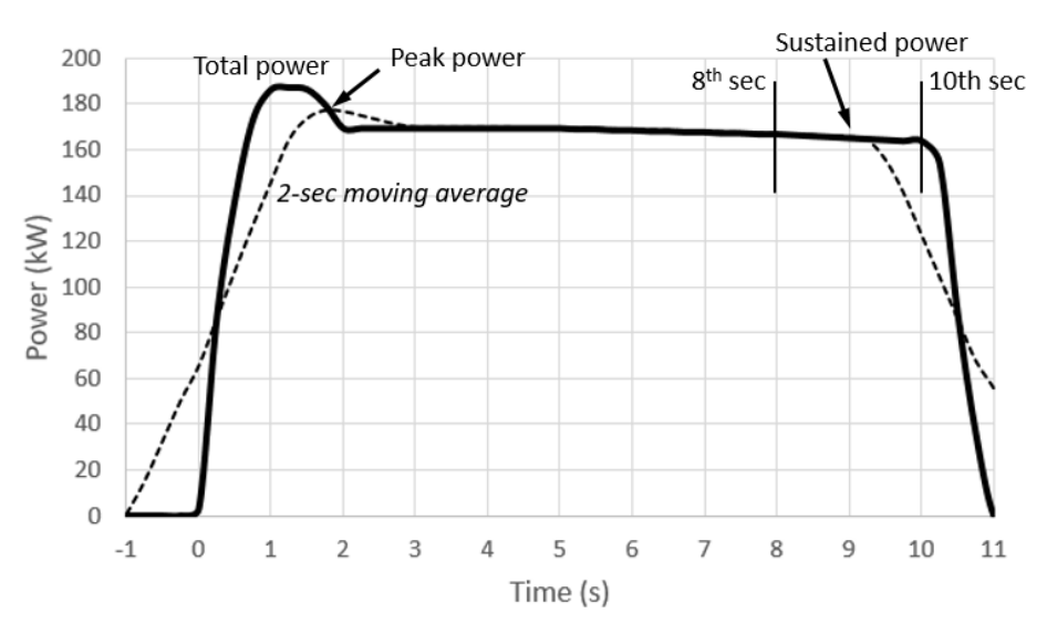
36. Calculations are then performed to determine the system power according to TP1 or TP2. As shown in Figure 7, a "peak" power is defined as the maximum value of a 2-second moving average of the total power over a 10 second window beginning at the start of maximum accelerator command, and a "sustained" power is the average total power between the 8th and 10th seconds. Figure 7 Definition of peak and sustained power
36. 그런 다음 TP1 또는 TP2에 따라 시스템 출력을 결정하는 계산을 수행한다. [그림 7]에서 보듯, “피크(peak)” 출력은 최대 가속페달 지령 시작 시점부터 10초 구간에 걸친 총출력의 2초 이동평균의 최댓값으로 정의되고, “지속(sustained)” 출력은 8초~10초 사이의 평균 총출력이다.
—
그림 7. 피크 출력과 지속 출력의 정의 — 2초 이동평균의 최댓값(피크), 8~10초 구간 평균(지속)
4. ISO 방법론의 선정
37
37. The IWG on EVE recognized that the ISO method showed good comparability, flexibility, and verifiability. At the 22nd meeting of the IWG on EVE, the contracting parties reached consensus that the ISO approach presented the best option as a basis to fulfill the needs of the mandate.
37. EVE IWG는 ISO 방법이 우수한 비교 가능성, 유연성, 검증 가능성을 보인다고 인정하였다. 제22차 EVE IWG 회의에서 체약당사국들은 ISO 접근이 임무의 요구를 충족할 기반으로서 최선의 선택지라는 합의에 도달하였다.
5. 통합과 검증
38
38. The IWG on EVE then turned attention to aligning and integrating the ISO method with UN GTR No. 15, or developing a new GTR. There was some debate as to whether the GTR should select only one of the ISO test procedures (TP1 or TP2) or retain both options. It was generally decided that retaining both would be preferable because it would accommodate variations in vehicle instrumentation possibilities and differing laboratory capabilities or preferences.
38. 이어서 EVE IWG는 ISO 방법을 UN GTR 제15호와 정렬·통합할지, 아니면 새 GTR을 개발할지로 관심을 돌렸다. GTR이 ISO 시험 절차 중 하나(TP1 또는 TP2)만 선택할지, 둘 다 유지할지에 대한 논쟁이 있었다. 차량 계측 가능성의 차이와 시험소 역량·선호의 차이를 수용하기 위해 둘 다 유지하는 편이 바람직하다고 대체로 결정되었다.
39
39. The IWG on EVE recognized that retention of both procedures meant that differences between the two test results should be minimized in order to prevent inconsistent results and the opportunity for selective reporting (or "cherry picking").
39. EVE IWG는 두 절차를 모두 유지한다는 것이, 결과 불일치와 선택적 보고(“체리피킹”)의 여지를 방지하기 위해 두 시험 결과 간 차이를 최소화해야 함을 의미한다고 인식하였다.
40
40. In designing and validating the ISO method, the ISO committee placed strong emphasis on its practicability. Testing at the Japan Automotive Research Institute (JARI) indicated that the procedures delivered equivalent results for a variety of HEVs, although TP2 was thought to show somewhat greater variability than TP1. Discussion in the IWG suggested that the relative variability may be the result of TP2 being based entirely on measured data, while a large component of TP1 relies on a fixed value for engine power obtained from the UN Regulation No. 85 rated power. If so, then the relative variability may be a natural outcome of differences in the procedures.
40. ISO 방법 설계·검증에서 ISO 위원회는 실용성을 크게 강조하였다. JARI 시험은 다양한 HEV에 대해 두 절차가 동등한 결과를 낸다고 시사하였으나, TP2가 TP1보다 다소 큰 변동성을 보이는 것으로 여겨졌다. IWG 논의는 이 상대적 변동성이, TP2가 전적으로 측정 데이터에 기반하는 반면 TP1은 상당 부분을 UN 규정 제85호 정격출력에서 얻은 고정 엔진출력값에 의존하기 때문일 수 있다고 보았다. 그렇다면 이 변동성은 절차 차이에서 비롯되는 자연스러운 결과일 수 있다.
41
41. The IWG on EVE recognized that additional validation testing would be necessary to assess this and other potential sources of variability, and also to validate the ability of the aligned ISO method to fulfil the specific needs of a regulatory application.
41. EVE IWG는 이와 기타 잠재적 변동 원인을 평가하고, 정렬된 ISO 방법이 규제 적용의 구체적 요구를 충족할 능력을 검증하기 위해 추가 검증시험이 필요하다고 인식하였다.
42
42. Several contracting parties volunteered to perform validation testing, including Environment and Climate Change Canada (ECCC), Joint Research Centre (JRC), U. S. Environmental Protection Agency (EPA), and KATRI.
42. 여러 체약당사국이 검증시험 수행을 자원하였으며, 여기에는 캐나다 환경기후변화부(ECCC), 공동연구센터(JRC), 미국 환경보호청(EPA), 그리고 KATRI가 포함되었다.
43
43. A first phase of the validation program was initiated at the April 2018 IWG on EVE meeting in Tokyo. Japan reviewed the testing performed on three HEVs in conjunction with development of the ISO standard in 2016. A matrix of additional HEVs that were available for testing was compiled. US EPA offered to perform testing of a Belted Alternator Starter (BAS) hybrid and a power split PHEV. Canada offered to perform testing of a later generation power split HEV, a P2 hybrid, and a two-motor PEV. KATRI offered to perform testing on a P2 hybrid. JRC offered to perform testing on two parallel hybrid vehicles provided by representatives from Volvo and Hyundai.
43. 검증 프로그램의 1단계는 2018년 4월 도쿄 EVE IWG 회의에서 착수되었다. 일본은 2016년 ISO 표준 개발과 연계해 3대의 HEV에 대해 수행한 시험을 검토하였다. 시험 가능한 추가 HEV 매트릭스가 작성되었다. 미국 EPA는 벨트구동 교류발전기 시동기(BAS) 하이브리드와 동력분기 PHEV 시험을, 캐나다는 후기 세대 동력분기 HEV·P2 하이브리드·2모터 PEV 시험을, KATRI는 P2 하이브리드 시험을, JRC는 볼보와 현대 측이 제공한 두 대의 병렬 하이브리드 시험을 제안하였다.
44
44. Japan arranged for consultation with the engineer who performed the ISO validation tests in Japan. A detailed technical report on this testing had been prepared in Japanese. Canada agreed to arrange for translation of the report into English. JRC scheduled an initial round of testing at the facilities in Ispra, Italy in 2018, which was attended by representatives from USA and Japan as well as technical support personnel from Volvo and Hyundai.
44. 일본은 ISO 검증시험을 수행한 엔지니어와의 협의를 주선하였다. 이 시험에 대한 상세 기술보고서는 일본어로 작성되어 있었다. 캐나다가 보고서의 영어 번역을 주선하기로 합의하였다. JRC는 2018년 이탈리아 이스프라 시설에서 1차 시험을 일정에 넣었고, 여기에 미국·일본 대표와 볼보·현대의 기술지원 인력이 참석하였다.
45
45. Due to the short time frame available, and the knowledge that the ISO committee had already performed significant validation, the validation testing focused primarily on practicability of the procedure as currently written, and the effect of default assumptions and available flexibilities on the consistency of the results. To save time, testing was limited to vehicles that were readily available at the participating test labs and calculations were performed using the specified default values for K (later renamed K1) and ηgb (renamed K2). In some cases, measurements were gathered from onboard systems rather than instrumentation due to resource constraints. While the measurements were believed to be sufficiently accurate, it was not always possible to validate onboard measurements for accuracy.
45. 가용 시간이 짧고 ISO 위원회가 이미 상당한 검증을 수행했음을 고려하여, 검증시험은 주로 현재 작성된 절차의 실용성과, 기본 가정·허용된 유연성이 결과 일관성에 미치는 영향에 초점을 맞추었다. 시간 절약을 위해 시험은 참여 시험소에서 쉽게 구할 수 있는 차량으로 한정되었고, 계산은 K(이후 K1으로 개칭)와 ηgb(K2로 개칭)의 지정 기본값을 사용해 수행되었다. 일부 경우 자원 제약으로 계측 대신 온보드 시스템에서 측정값을 수집하였다. 그 측정값은 충분히 정확하다고 믿어졌으나, 온보드 측정의 정확도를 항상 검증할 수 있었던 것은 아니다.
46
46. The results of the first phase of validation revealed significant and unexpected differences between the results of TP1 and TP2 for many of the vehicles tested. Accordingly, the work of the IWG began to focus on identifying the sources of these differences, their implications, and how to reduce or eliminate them.
46. 1단계 검증 결과, 시험한 많은 차량에서 TP1과 TP2 결과 간에 유의하고 예상치 못한 차이가 드러났다. 이에 따라 IWG의 작업은 이러한 차이의 원인, 그 함의, 그리고 이를 줄이거나 제거하는 방법을 식별하는 데 집중되기 시작하였다.
6. 검증 1단계에서 관찰된 TP1·TP2 차이의 원인
47
47. The IWG on EVE identified several potential causes for the observed differences: (a) Variation in accuracy of default values for K1 and K2 as applied to specific vehicle models. (b) Uncertainty in accuracy of measurements and measurement options. (c) Variation in power of production engines compared to UN Regulation No. 85 test results. (d) Influence of powertrain architecture on necessary measurements to perform TP1 or TP2 in an equivalent manner. (a) Default values for K1 and K2
47. EVE IWG는 관찰된 차이의 잠재적 원인을 여러 가지로 식별하였다. - (a) 특정 차종에 적용된 K1·K2 기본값의 정확도 편차. - (b) 측정 및 측정 옵션의 정확도 불확실성. - (c) UN 규정 제85호 시험 결과 대비 양산 엔진 출력의 편차. - (d) TP1·TP2를 동등하게 수행하는 데 필요한 측정에 대한 파워트레인 구조의 영향.
(a) K1·K2 기본값
48
48. For a given powertrain architecture and vehicle model, the relative accuracy of the fixed default values for K1 and K2 are likely to vary, leading to differences in the accuracy with which each TP accounts for losses, and thereby leading to a difference in the results.
48. 주어진 파워트레인 구조와 차종에 대해 K1·K2 고정 기본값의 상대적 정확도는 달라질 가능성이 높으며, 이는 각 TP가 손실을 반영하는 정확도의 차이로, 나아가 결과의 차이로 이어진다.
49
49. In particular, the default K1 value of 0.85 sometimes appeared to produce lower power ratings for TP1, depending on the fraction of total power contributed by electricity. For one vehicle that was propelled entirely by electrical power, the power rating delivered by TP1 was smaller than the power measured at the wheels (which would erroneously suggest a drivetrain efficiency greater than 100 percent). Modifying the K1 value to a different value that was still consistent with the powertrain design made the result much closer to that of TP2.
49. 특히 K1 기본값 0.85는 총출력 중 전기가 기여하는 비율에 따라 TP1의 출력 정격을 더 낮게 산출하는 것처럼 보이는 경우가 있었다. 전적으로 전기로 추진되는 한 차량의 경우 TP1이 산출한 출력 정격이 바퀴에서 측정한 출력보다 작았는데(이는 구동계 효율이 100%를 초과한다는 잘못된 시사가 된다), K1 값을 파워트레인 설계와 여전히 부합하는 다른 값으로 수정하니 결과가 TP2에 훨씬 가까워졌다.
50
50. For some powertrain architectures, the applicable default K2 factor for TP2 was unclear. Two of the test laboratories independently chose to employ different K2 values for an architecture that included series and parallel elements.
50. 일부 파워트레인 구조에서는 TP2에 적용할 기본 K2 계수가 불분명하였다. 두 시험소가 직렬·병렬 요소를 포함한 한 구조에 대해 독립적으로 서로 다른 K2 값을 선택하였다.
51
51. It was anticipated that the predefined list of default K2 factors may be insufficient to represent potential architectures that may emerge in the future. In particular, Japan pointed out that it is uncertain whether the default value for K2 would apply to different variations in power split hybrid architectures. (b) Accuracy of measurements
51. 미리 정의된 기본 K2 계수 목록이 장래 등장할 잠재적 구조를 대표하기에 불충분할 수 있다고 예상되었다. 특히 일본은 동력분기 하이브리드 구조의 여러 변형에 대해 K2 기본값이 적용될지 불확실하다고 지적하였다.
(b) 측정의 정확도
52
52. Some of the validation tests relied on TP1 measurements that were based on onboard network data that could not be verified because physical instrumentation for current and voltage was not available. While believed to be accurate, any inaccuracy could have contributed to the difference between TP1 and TP2.
52. 일부 검증시험은 전류·전압의 물리적 계측이 없어 검증할 수 없는 온보드 네트워크 데이터에 기반한 TP1 측정에 의존하였다. 정확하다고 믿어졌으나, 어떤 부정확성이라도 TP1·TP2 차이에 기여했을 수 있다.
53
53. Measurements for TP2 were taken from dynamometer rollers and therefore included tire losses. While the test procedure permitted the use of roller data if tire losses were accounted for, it did not specify a method for determining tire losses. Evidence of tire slippage was observed, which may have introduced additional unaccounted losses. (c) Variability of UN Regulation No. 85 engine power
53. TP2 측정은 동력계 롤러에서 취해져 타이어 손실을 포함하였다. 시험 절차는 타이어 손실을 보정하면 롤러 데이터 사용을 허용했으나, 타이어 손실 결정 방법을 명시하지 않았다. 타이어 슬립의 증거가 관찰되었고, 이는 추가적인 미반영 손실을 유발했을 수 있다.
(c) UN 규정 제85호 엔진 출력의 변동성
54
54. TP1 may be affected by allowable variation in engine power from UN Regulation No. 85 test results. According to Section 5.4 of UN Regulation No. 85 (Interpretation of results), the declared power output of production engines certified under UN Regulation No. 85 is permitted to vary by ± 2 percent from the test result, suggesting that some error is possible even if the measured engine speed and intake manifold pressure match perfectly with those reported in UN Regulation No.
54. TP1은 UN 규정 제85호 시험 결과 대비 허용되는 엔진 출력 편차의 영향을 받을 수 있다. UN 규정 제85호 5.4절(결과 해석)에 따르면 동 규정으로 인증된 양산 엔진의 신고 출력은 시험 결과로부터 ±2% 변동이 허용되며, 이는 측정된 엔진 회전수와 흡기 매니폴드 압력이 동 규정 보고값과 완벽히 일치하더라도 일부 오차가 가능함을 시사한다. 이 불확실성은 TP1에 고유하므로 관찰된 TP1·TP2 변동에 기여할 수 있다.
55
55. Further, TP1’s estimation of engine power based on measured speed relies on the assumption that the engine is operating at its maximum power for that speed, and that the power can be accurately reconstructed by reference to engine test results (e.g. UN Regulation No. 85). Measurements of intake manifold pressure and fuel flow rate are compared to the engine test result to verify that the engine operating state is consistent with maximum power. However, the test procedure did not specify the permissible variation, leading to uncertainty in the engine power portion of TP1.
55. 나아가 TP1의 측정 회전수 기반 엔진 출력 추정은, 엔진이 그 회전수에서 최대출력으로 운전 중이며 출력을 엔진 시험 결과(예: UN 규정 제85호) 참조로 정확히 재구성할 수 있다는 가정에 의존한다. 흡기 매니폴드 압력과 연료 유량을 엔진 시험 결과와 비교하여 엔진 운전 상태가 최대출력과 일치하는지 검증한다. 그러나 시험 절차가 허용 편차를 명시하지 않아 TP1의 엔진 출력 부분에 불확실성이 생겼다.
56
56. Some experts noted that intake manifold pressure is not highly sensitive to power output at the constant engine speed that results from the procedure, and therefore it is not highly effective at confirming the result. It was recommended that measurement of fuel flow rate also be required for verification of UN Regulation No. 85 engine power. (d) Influence of powertrain architecture
56. 일부 전문가는 절차에서 비롯되는 일정한 엔진 회전수에서 흡기 매니폴드 압력이 출력에 그리 민감하지 않으므로 결과 확인에 효과적이지 않다고 지적하였다. UN 규정 제85호 엔진 출력 검증을 위해 연료 유량 측정도 요구할 것이 권고되었다.
(d) 파워트레인 구조의 영향
57
57. ISO 20762 does not mention the concept of reference points, although reference points are implied by the details of the procedure. When the concept of reference points was introduced and applied rigorously, it was found that for some powertrain architectures, the then-prescribed calculations for TP1 and TP2 may have been estimating power at slightly different reference points, leading to variation between the results.
57. ISO 20762는 기준점 개념을 언급하지 않으나, 절차의 세부에 기준점이 함축되어 있다. 기준점 개념을 도입해 엄밀히 적용하니, 일부 파워트레인 구조에서는 당시 규정된 TP1·TP2 계산이 서로 약간 다른 기준점의 출력을 추정하고 있었고, 이것이 결과 간 변동으로 이어졌음이 발견되었다.
58
58. As shown in Figure 8, both TP1 and TP2 apply well to a parallel P2 HEV. Here, the system power is the sum of the power at R1 and R2. The K1 and K2 factors represent the conversion efficiencies of simple component combinations, and so are relatively simple to determine and verify. TP1 determines engine power at R1 by reference to speed and UN Regulation No. 85 results, and determines the power at R2 by measuring power from the REESS (subtracting accessory power) and applying the K1 efficiency factor. Alternatively, TP2 determines the sum of the power at R1 and R2 by measuring power at the axle shafts and applying K2. If the applicable measurements and K factors are equally accurate, then for this powertrain architecture, TP1 and TP2 should always deliver the same answer for the sum of R1 and R2. Note: measurement point for TP2 represents both axle shafts.
58. [그림 8]에서 보듯, TP1과 TP2 모두 병렬 P2 HEV에 잘 적용된다. 여기서 시스템 출력은 R1과 R2 출력의 합이다. K1·K2 계수는 단순 구성품 조합의 변환 효율을 나타내므로 비교적 간단히 결정·검증된다. TP1은 회전수와 UN 규정 제85호 결과를 참조해 R1의 엔진 출력을 결정하고, REESS 출력을 측정(보조 출력 차감)한 뒤 K1 효율계수를 적용해 R2 출력을 결정한다. 대안으로 TP2는 차축 출력을 측정하고 K2를 적용해 R1+R2 합을 결정한다. 적용된 측정과 K 계수가 동등하게 정확하다면, 이 구조에서 TP1과 TP2는 항상 R1+R2 합에 대해 동일한 답을 내야 한다.
—
그림 8. 전기기계 1개를 가진 병렬 P2 하이브리드 — TP1·TP2 모두 측정 가능
59
59. However, in the case of some other architectures, the specified measurements for TP1 or TP2 may be difficult to convert to a common reference point.
59. 그러나 일부 다른 구조에서는 TP1 또는 TP2의 지정 측정값을 공통 기준점으로 변환하기 어려울 수 있다.
60
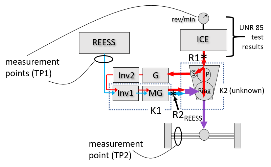
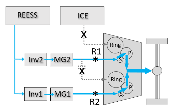
60. As shown in Figure 9, the Toyota Hybrid System (THS) utilizes a planetary gear set with multiple inputs and outputs. Under maximum power demand, engine power enters through the planet gear carrier (P), then is split between the ring gear (where it goes directly to the wheels) and the sun gear S (where it enters a series path that eventually delivers additional torque to the ring gear for delivery to the wheels). Figure 9 Power split hybrid, ambiguous under TP2 P = planet carrier and gears; S = sun gear; Ring = ring gear Note: measurement point for TP2 represents both axle shafts.
60. [그림 9]에서 보듯, 도요타 하이브리드 시스템(THS)은 다중 입출력을 가진 유성기어 세트를 사용한다. 최대출력 요구 시 엔진 출력은 유성기어 캐리어(P)를 통해 들어와 링기어(직접 바퀴로 전달)와 선기어 S(직렬 경로로 들어가 결국 추가 토크를 링기어로 전달) 사이에서 분배된다.
—
그림 9. 동력분기 하이브리드 — TP2에서 모호함. P=유성캐리어/기어, S=선기어, Ring=링기어
61
61. With careful consideration, reference points that are most comparable to a conventional vehicle can be identified. Reference point R1 represents where mechanical power from the engine is first produced. From here, the engine power splits to the series path and the direct-to-wheels path, which together may be considered as a sort of electromechanical transmission, and therefore, as with the transmission of a conventional vehicle, is not subject to further accounting.
61. 신중히 고려하면 종래 차량에 가장 비교 가능한 기준점을 식별할 수 있다. 기준점 R1은 엔진의 기계적 출력이 처음 생성되는 지점을 나타낸다. 여기서 엔진 출력은 직렬 경로와 직접-바퀴 경로로 분기되며, 이 둘은 함께 일종의 전기기계식 변속기로 볼 수 있으므로, 종래 차량의 변속기와 마찬가지로 추가 계산 대상이 아니다.
62
62. Another reference point must be established to account for the contribution of the REESS. REESS power is first produced as mechanical power at the output shaft of motorgenerator MG; however, at this point it has been combined with power contributed by the engine series path (which is already accounted for via R1). To prevent double counting, the second reference point is therefore called R2REESS, and represents the portion of MG power that is attributable to the REESS.
62. REESS의 기여를 반영하기 위해 또 다른 기준점을 설정해야 한다. REESS 출력은 모터-제너레이터 MG의 출력축에서 기계적 출력으로 처음 생성되나, 이 지점에서 이미 엔진 직렬 경로의 출력(R1으로 이미 계산됨)과 결합되어 있다. 이중계산을 막기 위해 두 번째 기준점을 R2REESS라 부르며, 이는 MG 출력 중 REESS에 귀속되는 부분을 나타낸다.
63
63. TP1 is straightforward for this architecture. The power at R1 is determined from UN Regulation No. 85 results, and R2REESS is the measured REESS power multiplied by K1 (where K1 is the electrical conversion efficiency of the total power flow through Inv1 and MG). System power is the sum of R1 and R2REESS.
63. TP1은 이 구조에 대해 간단하다. R1의 출력은 UN 규정 제85호 결과로 결정하고, R2REESS는 측정된 REESS 출력에 K1(Inv1과 MG를 통과하는 전체 전력흐름의 전기 변환 효율)을 곱한 값이다. 시스템 출력은 R1과 R2REESS의 합이다.
64
64. TP2 is not as straightforward here. TP2 relies on a measure of total power at the axle shafts or wheel hubs, to which it seeks to apply a K2 efficiency factor to account for gearbox losses. But here, the power has arrived via two different paths from the engine, and a third path from the REESS, all of which have experienced different conversion efficiency. The combined power measurement at the axle does not identify the share of power along each path, so there is not enough information to reconstruct the power at R1 and R2REESS even if the conversion efficiency of each path is known.
64. TP2는 여기서 그리 간단하지 않다. TP2는 차축 또는 휠 허브에서의 총출력 측정에 의존하며 여기에 K2 효율계수를 적용해 기어박스 손실을 반영하려 한다. 그러나 여기서는 출력이 엔진으로부터 두 경로, REESS로부터 한 경로의 세 경로로 도착하며, 각 경로의 변환 효율이 다르다. 차축에서의 결합 출력 측정은 각 경로별 출력 비중을 식별하지 못하므로, 각 경로 변환 효율을 안다 해도 R1과 R2REESS의 출력을 재구성할 정보가 부족하다.
65
65. Another option might be to compute (R1+R2REESS) rather than each individually. This would require a "net" K2 factor that accounts for the total losses along all three paths. If all three paths had the same conversion efficiency, it would not be necessary to know the power along each path. But that is not the case here. While the manufacturer might be able to experimentally determine a "net" K2, it would not be possible to verify using the data that is collected by TP2. If the K2 factor were to represent anything other than this "net" factor, such as for example just the efficiency of the mechanical direct drive path, then it would not be reconstructing the power at either of the designated reference points.
65. 또 다른 선택지는 각각이 아니라 (R1+R2REESS)를 계산하는 것이다. 이는 세 경로의 총손실을 반영하는 “순(net)” K2 계수를 요구한다. 세 경로의 변환 효율이 모두 같다면 경로별 출력을 알 필요가 없겠으나, 여기서는 그렇지 않다. 제조사가 실험적으로 “순” K2를 구할 수는 있어도, TP2가 수집하는 데이터로는 검증이 불가능하다. K2 계수가 이 “순” 계수가 아닌 다른 것(예: 기계식 직접구동 경로의 효율만)을 나타낸다면, 지정된 어느 기준점의 출력도 재구성하지 못한다.
66
66. This is another way of saying that the original versions of TP1 and TP2, when applied to a power split hybrid, each determine the power at slightly different reference points. When considered individually, either of the results might be reasonable as a system power rating. However, they cannot be expected to be the same if they refer to different reference points.
66. 이는 곧, 동력분기 하이브리드에 적용된 원래 버전의 TP1·TP2가 각각 약간 다른 기준점의 출력을 결정한다는 말이다. 개별적으로 보면 어느 결과든 시스템 출력 정격으로서 합리적일 수 있다. 그러나 서로 다른 기준점을 가리킨다면 같은 값을 기대할 수 없다.
67
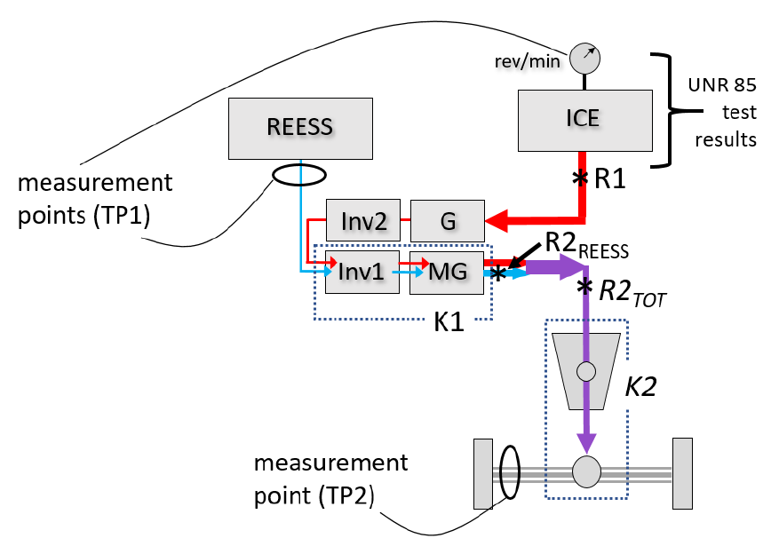
67. This situation is seen more clearly in Figure 10, for a pure series hybrid. As before, the reference points are where mechanical power is first produced, at R1 and R2REESS. TP1 would determine the mechanical power from the engine (at R1) and the REESS contribution at motor MG (at R2REESS). In contrast, TP2 would measure the power at the axle shafts and apply a K2 factor to account for losses in the gearbox and differential, thereby reaching a different reference point (here called R2TOT) and reporting that as the system power. The power at R2TOT is bound to be different than at (R1 + R2REESS). Further, RTOT is inconsistent as a reference point because it is not a point where mechanical power is first produced. Figure 10 Inconsistent reference points for TP1 and TP2 for pure series HEV Note: measurement point for TP2 represents both axle shafts.
67. 이 상황은 [그림 10]의 순수 직렬 하이브리드에서 더 명확히 드러난다. 앞서처럼 기준점은 기계적 출력이 처음 생성되는 R1과 R2REESS이다. TP1은 엔진의 기계적 출력(R1)과 모터 MG에서의 REESS 기여(R2REESS)를 결정한다. 반면 TP2는 차축 출력을 측정하고 K2를 적용해 기어박스·차동기어 손실을 보정하여 다른 기준점(여기서는 R2TOT)에 도달하고 이를 시스템 출력으로 보고한다. R2TOT의 출력은 (R1+R2REESS)와 다를 수밖에 없다. 또한 RTOT는 기계적 출력이 처음 생성되는 지점이 아니므로 기준점으로서 일관되지 않다.
—
그림 10. 순수 직렬 HEV에 대한 TP1·TP2의 불일치 기준점
68
68. Further, as a side effect, here the power measured by TP2 at R2TOT will always be lower than for TP1, because the power at R2TOT has been reduced by losses in the electrical Note: measurement point for TP2 represents both axle shafts.
68. 나아가 부작용으로, 여기서 TP2가 R2TOT에서 측정한 출력은 항상 TP1보다 낮은데, 이는 R2TOT의 출력이 전기 변환 경로(G+Inv2+Inv1+MG)의 손실만큼 감소한 반면 TP1은 이를 허용 가능한 변속기 손실의 일부로 간주하기 때문이다.
69
—
69. 기준점이 조화되더라도, 일부 파워트레인 구조는 둘 중 한 TP에 특별한 어려움을 줄 수 있다.
70
—
70. [그림 11]에서 보듯, TP1은 REESS에서 나가는 출력을 측정하나 이 출력이 하류에서 두 병렬 인버터/모터(Inv1/MG1, Inv2/MG2) 사이에 어떻게 분배되는지는 반영하지 못한다. 따라서 K1 계수가 두 인버터/모터 조합의 결합 손실을 모두 반영해야 한다. 제조사가 그런 계수를 실험적으로 구해 제공할 수는 있어도, 개별 전력흐름을 측정하지 않고는 효율 데이터로 독립 검증할 수 없다.
71
—
71. REESS 출력 대신 각 인버터로 들어가는 출력을 측정하고 각 인버터/모터 조합에 별도 K1 계수를 적용하는 편이 더 효과적이다. 이 경우 전력흐름이 알려지므로 각 K1 계수를 독립적으로 검증할 수 있다.
72
—
72. 반면 TP2는 정확한 K2 계수만 있으면 차축 측정 출력으로부터 합(R1+R2)을 결정하는 데 어려움이 없다.
—
그림 11. 모터 2개를 가진 병렬 P2 하이브리드 — TP1에 더 어려움. TP2 측정점은 양쪽 차축 대표
73
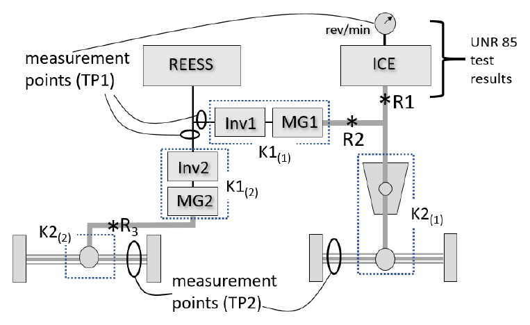
73. Figure 12 shows an example HEV with two powered axles. Here a four-wheel-drive dynamometer would be needed, and the power measured at each axle separately. The reference points on the first (right) axle are marked R1 and R2, and on the second (left) axle, R3. TP2 is straightforward for each axle (although it does require a unique K2 factor for each axle). TP1 can determine R1, R2, and R3 if the electrical measurement points include the inputs to each inverter (Inv1 and Inv2) and factors K1(1) and K1(2) are provided. Alternatively, TP1 can determine R1 and the sum (R2+R3) if the electrical measurement is at the REESS and the conversion efficiency of the two electrical paths can be combined or are the same. Figure 12 Vehicle with two powered axles Note: measurement points for TP2 represent both axle shafts.
73. [그림 12]는 두 개의 구동축을 가진 HEV 예시이다. 여기서는 4륜구동 동력계가 필요하며 각 차축의 출력을 따로 측정한다. 첫째(우측) 차축의 기준점은 R1·R2, 둘째(좌측) 차축은 R3로 표시된다. TP2는 각 차축에 대해 간단하다(단 차축마다 고유 K2 계수 필요). TP1은 전기 측정점이 각 인버터(Inv1, Inv2) 입력을 포함하고 계수 K1(1)·K1(2)가 제공되면 R1·R2·R3를 결정할 수 있다. 대안으로, 전기 측정이 REESS에서 이루어지고 두 전기 경로의 변환 효율을 결합할 수 있거나 동일하다면 TP1은 R1과 합(R2+R3)을 결정할 수 있다.
—
그림 12. 두 개의 구동축을 가진 차량
74
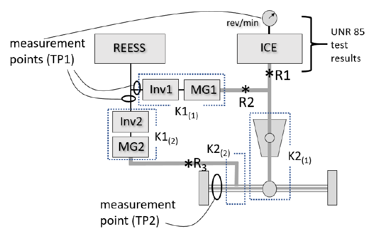
74. However, as shown in Figure 13, a small change to the configuration makes it very difficult to apply TP2. Here MG2 might represent a pair of wheel hub motor(s) which now contribute to powering the first axle. The power flow from the wheel hub motors at R3 is likely to experience a very high efficiency K2(2), while those entering the gearbox/differential from (R1+R2) experience a probably lower efficiency K2(1). Because TP2 measures only the combined power, at the axle, it is not possible to apply both K factors to the portion they represent. Figure 13 Configuration with difficulty for TP2 Note: measurement point for option 2 represents both axle shafts.
74. 그러나 [그림 13]에서 보듯, 구성을 약간만 바꾸면 TP2 적용이 매우 어려워진다. 여기서 MG2는 첫째 차축 구동에 기여하게 된 한 쌍의 휠허브 모터를 나타낼 수 있다. R3의 휠허브 모터 전력흐름은 매우 높은 효율 K2(2)를, 기어박스/차동기어로 들어가는 (R1+R2)는 아마 더 낮은 효율 K2(1)을 겪는다. TP2는 차축에서 결합 출력만 측정하므로 각 K 계수를 해당 부분에 적용하는 것이 불가능하다.
—
그림 13. TP2에 어려움이 있는 구성
75
75. The applicability of TP1 and TP2 can depend not only on the physical configuration of the powertrain, but also on the selected driving mode. Figure 14 and Figure 15 show two high-power modes of the Generation 2 Chevy Volt powertrain, one for a pure electric chargedepleting (CD) mode and another for a blended charge-sustaining (CS) mode.
75. TP1·TP2의 적용성은 파워트레인의 물리적 구성뿐 아니라 선택된 주행 모드에도 좌우될 수 있다. [그림 14]·[그림 15]는 2세대 쉐보레 볼트 파워트레인의 두 고출력 모드, 즉 순수 전기 충전-소모(CD) 모드와 혼합 충전-유지(CS) 모드를 보여준다.
76
76. In CD mode (Figure 14), both TP1 and TP2 can be performed (with certain assumptions). TP1 can determine both R1 and R2, assuming that the power into each inverter is measured, or the sum (R1+R2) if power from the REESS is measured and the conversion efficiency of both electrical conversion paths is the same and can thus be combined. TP2 can determine the sum (R1+R2) from the power measured at the axle, assuming that the efficiency of each sun-to-planet (S, P) gear path is the same. Figure 14 Volt Gen 2 charge-depleting Mode 2 (CD2)
76. CD 모드([그림 14])에서는 (특정 가정 하에) TP1·TP2 모두 수행 가능하다. TP1은 각 인버터 입력 출력을 측정하면 R1·R2를 각각, 또는 REESS 출력을 측정하고 두 전기 변환 경로 효율이 같아 결합 가능하면 합(R1+R2)을 결정할 수 있다. TP2는 각 선기어-유성(S, P) 기어 경로의 효율이 같다고 가정하면 차축 측정 출력으로부터 합(R1+R2)을 결정할 수 있다.
—
그림 14. 볼트 2세대 충전-소모 모드 2 (CD2)
77
77. However, in CS mode (Figure 15), the power flow paths are different. TP1 can still determine R1 and R2 from engine and REESS measurements. But in order for TP2 to determine the sum (R1+R2) as before, the efficiency of the Ring-to-planet and Sun-to-planet gear paths must be similar enough to be combined. Otherwise, the relative power contributed by the engine and the motor would be required, and it is not collected. Figure 15 Volt Gen 2 charge sustaining mode 2 (CS2)
77. 그러나 CS 모드([그림 15])에서는 전력흐름 경로가 다르다. TP1은 여전히 엔진·REESS 측정으로 R1·R2를 결정할 수 있다. 그러나 TP2가 이전처럼 합(R1+R2)을 결정하려면 링-유성 및 선-유성 기어 경로의 효율이 결합 가능할 만큼 충분히 유사해야 한다. 그렇지 않으면 엔진과 모터가 기여하는 상대 출력이 필요한데 이는 수집되지 않는다.
—
그림 15. 볼트 2세대 충전-유지 모드 2 (CS2)
78
78. At the 30th IWG on EVE meeting, the IWG requested that experts from VDA (German Association of the Automotive Industry) who were involved with development of the ISO procedure provide additional input on the observed differences between the results of TP1 and TP2. VDA delivered a presentation at the 31st IWG on EVE addressing this topic and provided recommendations for the second phase of validation testing.
78. 제30차 EVE IWG 회의에서 IWG는 ISO 절차 개발에 참여한 VDA(독일자동차산업협회) 전문가들에게 관찰된 TP1·TP2 결과 차이에 대한 추가 의견을 요청하였다. VDA는 제31차 EVE IWG에서 이 주제에 대한 발표를 하고 2단계 검증시험 권고안을 제공하였다.
79
79. The VDA experts acknowledged that some of the deviation could be the result of fixed, default K1 and K2 factors, but felt that it was also important to verify that the measurement requirements and accuracies described in ISO 20762 are followed.
79. VDA 전문가들은 일부 편차가 고정 기본 K1·K2 계수의 결과일 수 있음을 인정하면서도, ISO 20762에 기술된 측정 요건과 정확도가 준수되는지 검증하는 것도 중요하다고 보았다.
80
80. VDA also stated that TP1 and TP2 can be expected to give the same result for parallel hybrids, which is consistent with the discussion in the previous paragraphs.
80. VDA는 또한 병렬 하이브리드에 대해서는 TP1·TP2가 동일한 결과를 낼 것으로 기대된다고 진술하였으며, 이는 앞선 논의와 부합한다.
81
81. For pure series or mixed (power split) hybrids, VDA stated that TP1 will always give a higher result than TP2 because TP1 does not account for electrical conversion losses in the series portion. This observation has now been explained by the difference in the reference points implied by TP1 and TP2 for power split and pure series hybrids, as discussed in the previous paragraphs. Defining the reference points as depicted in Figure 9 addresses this concern, and means that TP2 becomes not applicable to this powertrain.
81. 순수 직렬 또는 혼합(동력분기) 하이브리드에 대해 VDA는, TP1이 직렬 부분의 전기 변환 손실을 반영하지 않으므로 TP1이 항상 TP2보다 높은 결과를 낼 것이라고 진술하였다. 이 관찰은 이제 동력분기·순수직렬 하이브리드에 대해 TP1·TP2가 함축하는 기준점 차이로 설명된다. [그림 9]처럼 기준점을 정의하면 이 우려가 해소되며, 이는 TP2가 이 파워트레인에 적용 불가가 됨을 의미한다.
7. TP1과 TP2의 조정
82
82. The IWG on EVE recognized that the need to reconcile TP1 and TP2 was a significant outstanding issue for the completion of the GTR. At the 30th meeting of the IWG on EVE in Stockholm, the IWG considered several options for completing the GTR.
82. EVE IWG는 TP1·TP2를 조정해야 할 필요가 GTR 완성의 중요한 미해결 쟁점임을 인식하였다. 스톡홀름에서 열린 제30차 EVE IWG 회의에서 IWG는 GTR 완성을 위한 여러 선택지를 검토하였다.
83
83. One possibility was to accept the difference between TP1 and TP2, and add interpretive text to the GTR to help users understand the difference. This would maintain the flexibility of the procedure, minimize divergence from ISO 20762, and reduce the likelihood that the difference could be misunderstood or deliberately misused. This option found little support.
83. 한 가지 가능성은 TP1·TP2의 차이를 받아들이고, 사용자가 차이를 이해하도록 GTR에 해설 텍스트를 추가하는 것이었다. 이는 절차의 유연성을 유지하고 ISO 20762로부터의 이탈을 최소화하며 차이가 오해되거나 고의로 악용될 가능성을 줄인다. 이 선택지는 거의 지지받지 못했다.
84
84. Another possibility was to eliminate the difference by modifying the GTR to define only a single possible result, rather than two. This might be done by any of: (a) Including only TP1 or TP2 in the GTR; (b) Requiring both TP1 and TP2, and reporting the average, the lower, or the higher of the two; (c) Retaining the nominal choice of TP1 or TP2, but validating the result by performing the other TP as a consistency check; (d) Specifying TP1 for some HEV architectures and TP2 for others.
84. 또 다른 가능성은 GTR을 수정하여 두 개가 아니라 단일 결과만 정의함으로써 차이를 제거하는 것이었다. 이는 다음 중 하나로 가능하다. - (a) GTR에 TP1 또는 TP2 중 하나만 포함; - (b) TP1·TP2 모두 요구하고 둘의 평균/낮은 값/높은 값을 보고; - (c) 명목상 TP1 또는 TP2를 선택하되, 다른 TP를 일관성 점검으로 수행하여 결과를 검증; - (d) 일부 HEV 구조에는 TP1, 다른 구조에는 TP2를 지정.
85
85. (a) The IWG was reluctant to eliminate either TP1 or TP2 entirely, due in part to the flexibility it affords, and preferences among members for one or the other procedure.
85. (a) IWG는 유연성과 회원국별 선호 때문에 TP1 또는 TP2를 완전히 제거하기를 꺼렸다.
86
86. (b, c) The IWG was reluctant to require both TPs to be performed because this would increase the test burden. Also, it was noted that the best choice among an average, lower, or higher of the two results would depend on the intended purpose of the measure. For downscaling and classification under WLTP, selecting the higher figure might be preferable because it would prevent excessive downscaling. But for customer information, the lower figure might be preferable to prevent exaggerating the available power. It was unclear if there was a valid technical justification for selecting either figure, or an average of the two, when it remained uncertain which result is most accurate for a given vehicle.
86. (b, c) IWG는 시험 부담 증가를 이유로 두 TP를 모두 요구하기를 꺼렸다. 또한 평균/낮은 값/높은 값 중 최선의 선택은 측정의 의도된 목적에 달려 있다고 지적되었다. WLTP의 다운스케일링·분류에는 과도한 다운스케일링을 막기 위해 높은 값이 바람직할 수 있으나, 소비자 정보에는 가용 출력 과장을 막기 위해 낮은 값이 바람직할 수 있다. 특정 차량에 어느 결과가 가장 정확한지 불확실한 상황에서 어느 한 값이나 평균을 택할 타당한 기술적 근거가 있는지 불분명하였다.
87
87. (d) The IWG remained open to the possibility of assigning TP1 and TP2 to specific powertrain types, given a clear technical justification.
87. (d) IWG는 명확한 기술적 근거가 있다면 특정 파워트레인 유형에 TP1·TP2를 배정할 가능성에 열려 있었다.
88
88. A final possibility was to modify the procedure to minimize the difference between TP1 and TP2 as much as possible.
88. 마지막 가능성은 절차를 수정하여 TP1·TP2 차이를 최대한 최소화하는 것이었다.
89
89. Because the problem is essentially one of physics, it should be possible to define TP1 and TP2 so that they deliver comparable results in all cases, if the following is true: (a) the power flows in the vehicle are correctly understood, (b) the reference points are correctly identified and consistent under both TP1 and TP2, and (c) the measurements and K factors are sufficiently accurate to estimate the power at the reference points.
89. 이 문제는 본질적으로 물리학의 문제이므로, 다음이 참이라면 모든 경우에 TP1·TP2가 비교 가능한 결과를 내도록 정의하는 것이 가능해야 한다: (a) 차량의 전력흐름이 올바로 이해되고, (b) 기준점이 올바로 식별되어 TP1·TP2에서 일관되며, (c) 측정과 K 계수가 기준점 출력을 추정하기에 충분히 정확할 것.
90
90. The question is to what degree the procedures for TP1 and TP2 can provide for this outcome while remaining practical to implement. For example, if successfully applying TP1 sometimes requires instrumentation of several inverter inputs rather than only the REESS output, or if successfully applying TP2 requires knowledge of relative power flows that are not measurable at the axle, the instrumentation burden may become prohibitive.
90. 문제는 TP1·TP2 절차가 실용성을 유지하면서 이 결과를 어느 정도 달성할 수 있느냐이다. 예컨대 TP1을 성공적으로 적용하는 데 REESS 출력만이 아니라 여러 인버터 입력의 계측이 필요하거나, TP2 적용에 차축에서 측정 불가한 상대 전력흐름 지식이 필요하다면, 계측 부담이 과도해질 수 있다.
91
91. At the 30th and 31st IWG on EVE meetings it was generally agreed that the difference between TP1 and TP2 should be reduced as much as possible by modifying the procedures, and that limiting certain architectures to TP1 or TP2 could also be considered. Several proposed modifications were identified to be evaluated in a second phase of validation testing.
91. 제30·31차 EVE IWG 회의에서, 절차 수정으로 TP1·TP2 차이를 최대한 줄이고 특정 구조를 TP1 또는 TP2로 한정하는 것도 검토할 수 있다는 데 대체로 합의하였다. 2단계 검증시험에서 평가할 여러 제안 수정사항이 식별되었다.
8. 절차에 대한 수정
92
92. The IWG reached consensus on several proposed modifications to reduce the difference between TP1 and TP2: (a) The option to use default K factors was replaced with a requirement that the manufacturer provide accurate and verifiable K factors specific to the vehicle under test. (b) The option to conduct TP2 using chassis dynamometer roller data was removed, in favor of axle or wheel hub instrumentation for torque and speed, or a hub dynamometer. (c) The procedure was clarified to require that current and voltage, if obtained from onboard systems, must be shown to be accurate (TP1).
92. IWG는 TP1·TP2 차이를 줄이기 위한 여러 제안 수정사항에 합의하였다. - (a) 기본 K 계수 사용 옵션을, 제조사가 시험 차량에 특정한 정확하고 검증 가능한 K 계수를 제공하도록 하는 요건으로 대체. - (b) 섀시 동력계 롤러 데이터로 TP2를 수행하는 옵션을 제거하고, 토크·속도용 차축·휠허브 계측 또는 허브 동력계를 사용하도록 함. - (c) 온보드 시스템에서 얻은 전류·전압은 정확함이 입증되어야 한다는 점을 명확화(TP1).
93
93. The drafting group also proposed several changes to be trialed in the second validation phase: (a) To reduce the possibility of variation, five repetitions of the power test are conducted and an average taken of the last four results (see paragraph 6.8.7.). (b) Applicability guidelines were added to determine the permissible application of TP1 and TP2 based on aspects of the power flows between the measurement points and the reference points, and any need for additional instrumentation to enable one or the other TP (see paragraph 6.1.3.). (c) A requirement was added for the manufacturer to document the flow of propulsion power through the powertrain of the vehicle during the maximum power condition, the proposed measurement points and reference points, and applicable K factors for TP1 or TP2 (see paragraph 6.1.1.1.). (d) The term "reference point" was introduced and defined. Guidelines for identifying reference points are provided in Annex 1.
93. 기초안 작성 그룹은 2단계 검증에서 시험할 여러 변경도 제안하였다. - (a) 변동 가능성을 줄이기 위해 출력 시험을 5회 반복하고 마지막 4회 결과의 평균을 취함(6.8.7. 참조). - (b) 측정점과 기준점 사이 전력흐름의 특성, 그리고 한쪽 TP를 가능케 하는 추가 계측 필요성에 근거하여 TP1·TP2의 허용 적용을 결정하는 적용성 지침 추가(6.1.3. 참조). - (c) 최대출력 조건에서 차량 파워트레인을 통과하는 추진 출력의 흐름, 제안 측정점·기준점, TP1·TP2용 적용 K 계수를 제조사가 문서화하도록 하는 요건 추가(6.1.1.1. 참조). - (d) “기준점” 용어 도입·정의. 기준점 식별 지침을 부속서 1에 제공.
94
94. The new requirement that K factors be furnished by the manufacturer means that it must be possible for the manufacturer to determine the relevant K factor, and for a third party to verify it by a standard method.
94. K 계수를 제조사가 제공해야 한다는 새 요건은, 제조사가 해당 K 계수를 결정할 수 있어야 하고 제3자가 표준 방법으로 이를 검증할 수 있어야 함을 의미한다.
95
95. The IWG considered that for TP1, test standards exist for the measurement of inverter and motor efficiency (K1), which could be used by the manufacturer to derive the K1 factor as well as by a third party to verify it. However, no similar test standard exists for gearbox efficiency (K2).
95. IWG는 TP1의 경우 인버터·모터 효율(K1) 측정을 위한 시험 표준이 존재하여, 제조사가 K1 계수를 도출하고 제3자가 검증하는 데 사용할 수 있다고 보았다. 그러나 기어박스 효율(K2)에 대해서는 유사한 시험 표준이 없다.
96
96. VDA was asked to provide a recommendation for a standard method for determining K2 for TP2. VDA recommended that any of various engineering methods could be employed, based on measurement of power in and power out on a test bench, and dividing output power by input power.
96. VDA에 TP2용 K2 결정 표준 방법 권고를 요청하였다. VDA는 시험대에서 입력 출력·출력 출력을 측정하고 출력을 입력으로 나누는 다양한 공학적 방법을 사용할 수 있다고 권고하였다.
97
97. The IWG also considered a proposal that a K2 factor might be determined (or verified) by performing TP1 using a known accurate K1 factor, and then solving for K2 by setting the result of TP1 equal to the result of TP2. A similar tactic might also be usable for internal validation of a test result. This approach was to be further evaluated with data from the second phase of validation.
97. IWG는 또한, 정확한 K1 계수로 TP1을 수행한 뒤 TP1 결과를 TP2 결과와 같게 놓아 K2를 푸는 방식으로 K2 계수를 결정(또는 검증)할 수 있다는 제안을 검토하였다. 유사한 방법이 시험 결과의 내부 검증에도 쓰일 수 있다. 이 접근은 2단계 검증 데이터로 추가 평가될 예정이었다.
9. 2단계 검증시험
98
98. The test laboratories were requested to implement a second phase of validation testing, with the following changes to the test program: (a) Conduct TP2 with torque and speed data from torque and speed sensors rather than dynamometer roller data. (b) Conduct TP1 with current and voltage data collected from current and voltage instrumentation, in addition to onboard data. (c) If more than one electrical power path is present downstream of the battery, then instrument the inputs to each inverter (if possible). (d) Seek measurements of electrical power to non-propulsion accessories. (e) Improve precision of wheel speed and dynamometer roller speed to identify presence of wheel slippage. (f) If significant wheel slippage is observed, add weight to the vehicle to eliminate it, particularly if slippage might affect the shifting or other behavior of the vehicle.
98. 시험소들에 다음 변경을 포함한 2단계 검증시험 시행을 요청하였다. - (a) 동력계 롤러 데이터가 아닌 토크·속도 센서의 토크·속도 데이터로 TP2 수행. - (b) 온보드 데이터에 더하여 전류·전압 계측의 전류·전압 데이터로 TP1 수행. - (c) 배터리 하류에 둘 이상의 전기 출력 경로가 있으면 (가능하면) 각 인버터 입력을 계측. - (d) 비추진 보조장치로 가는 전기출력 측정 모색. - (e) 휠 슬립 존재를 식별하도록 휠 속도·동력계 롤러 속도 정밀도 향상. - (f) 유의한 휠 슬립이 관찰되면(특히 슬립이 변속 등 차량 거동에 영향을 줄 수 있는 경우) 차량에 중량을 추가해 제거.
99
99. In most cases, K factors were not expected to be available. Outside of a type approval or certification context, manufacturers are unlikely to have suitable data already prepared and little incentive to produce it. Even if K factors were provided, their usefulness in validating the procedure would be limited unless they could be independently verified (which was not within the scope of the program). Instead, the results were to be evaluated by considering the ability for reasonable K factors to make the results of each TP consistent with each other.
99. 대부분의 경우 K 계수는 가용하지 않을 것으로 예상되었다. 형식승인·인증 맥락 밖에서 제조사는 적합한 데이터를 미리 준비하고 있을 가능성이 낮고 이를 생산할 유인도 거의 없다. K 계수가 제공되더라도 독립 검증이 불가능하면 절차 검증에서의 유용성은 제한적이다(독립 검증은 프로그램 범위 밖이었다). 대신, 합리적 K 계수가 각 TP 결과를 서로 일관되게 만들 수 있는지를 고려하여 결과를 평가하기로 하였다.
100
100. For the second phase of validation, ECCC tested: a 2018 BMW 530e (OVC-HEV), a 2016 Chevrolet Volt (OVC-HEV), a 2018 Toyota Prius Prime (OVC-HEV), and a 2009 Saturn Vue (mild BAS NOVC-HEV). JRC expressed an intention of testing two additional vehicles, and as of Autumn 2019 were continuing efforts to procure suitable vehicles and provide them with necessary instrumentation. US EPA had intended to test two additional vehicles, but damage to one of the vehicles, and an unexpected difficulty with the funding mechanism for contract work necessary to instrument the vehicles, made it impossible for EPA to participate in the second phase.
100. 2단계 검증에서 ECCC는 2018년식 BMW 530e(OVC-HEV), 2016년식 쉐보레 볼트(OVC-HEV), 2018년식 도요타 프리우스 프라임(OVC-HEV), 2009년식 새턴 뷰(마일드 BAS NOVC-HEV)를 시험하였다. JRC는 추가 두 대 시험 의향을 밝히고 2019년 가을 기준 적합 차량 확보·계측을 계속 추진하였다. 미국 EPA는 추가 두 대 시험을 의도했으나, 한 차량의 손상과 차량 계측 계약작업 자금 메커니즘의 예상치 못한 어려움으로 2단계 참여가 불가능해졌다.
101
101. Results of the second phase began to become available in late 2019 and continued to be produced through March 2020. At an interim IWG on EVE teleconference on 12 December 2019, ECCC provided draft reports for the 2018 BMW 530e and the 2016 Chevy Volt, followed by final reports in March 2020. A report for the Saturn Vue was delivered in February 2020. As of March 2020 a draft report for the Prius Prime is awaiting completion.
101. 2단계 결과는 2019년 말부터 나오기 시작해 2020년 3월까지 계속 산출되었다. 2019년 12월 12일 중간 EVE IWG 화상회의에서 ECCC는 2018년식 BMW 530e와 2016년식 쉐보레 볼트의 초안 보고서를 제공했고, 2020년 3월 최종 보고서가 뒤따랐다. 새턴 뷰 보고서는 2020년 2월에 제출되었다. 2020년 3월 기준 프리우스 프라임 초안 보고서는 완성 대기 중이었다.
102
102. JRC provided test results for hub dyno testing and is progressing to provide results of wheel torque measurements on the same vehicle.
102. JRC는 허브 동력계 시험 결과를 제공했고 같은 차량의 휠 토크 측정 결과 제공을 진행 중이었다.
103
103. Throughout the test program, ECCC encountered difficulty obtaining UN Regulation No. 85 engine test results applicable to the vehicles tested. UN Regulation No. 85 results were obtained for the Toyota Prius Prime in January 2020, and for the European version of the BMW 530e in February 2020 (however, the vehicle tested was a North America vehicle for which the engine has a different torque specification). Because the Chevy Volt and the Saturn Vue are not EU-spec vehicles, UN Regulation No85 data was not available for these vehicles. For these reasons, TP1 could not be performed for these in exactly the manner prescribed.
103. 시험 프로그램 전반에서 ECCC는 시험 차량에 적용 가능한 UN 규정 제85호 엔진 시험 결과 확보에 어려움을 겪었다. 프리우스 프라임은 2020년 1월, 유럽형 BMW 530e는 2020년 2월에 UN 규정 제85호 결과를 확보했다(다만 시험 차량은 엔진 토크 사양이 다른 북미형이었다). 쉐보레 볼트와 새턴 뷰는 EU 사양 차량이 아니어서 UN 규정 제85호 데이터가 가용하지 않았다. 이런 이유로 이들에 대해서는 규정된 방식 그대로 TP1을 수행할 수 없었다.
104
104. As for TP2 results, ECCC found that the torque and speed measurement devices gave inconsistent results and in some cases malfunctioned. There is significant doubt as to whether the TP2 results are valid due to these difficulties.
104. TP2 결과의 경우, ECCC는 토크·속도 측정 장치가 일관되지 않은 결과를 내고 일부는 오작동함을 발견하였다. 이러한 어려움으로 TP2 결과의 타당성에 상당한 의문이 있다.
105
105. Although a direct comparison between TP1 and TP2 was therefore not possible in many cases, the second phase of validation revealed valuable recommendations regarding the practicability of the procedure and recommendations for improvement.
105. 따라서 많은 경우 TP1·TP2의 직접 비교가 불가능했으나, 2단계 검증은 절차의 실용성에 관한 가치 있는 권고와 개선 권고를 드러냈다.
106
106. Additionally, late results from JRC testing with a hub dynamometer have confirmed good agreement between TP1 and TP2 for a P2 hybrid configuration. Analysis of the data will continue to further validate this conclusion and for consideration in the development of future versions of this GTR. C. Technical rationale and justification Section C.1 describes the technical justification for the major specific differences between the procedure described in this GTR and the ISO 20762 procedure on which it was based. Section C.2 provides additional discussion of the basis upon which the IWG on EVE recommends the procedure as a whole.
106. 또한 JRC의 허브 동력계 시험 후기 결과는 P2 하이브리드 구성에 대해 TP1·TP2 간 양호한 일치를 확인하였다. 이 결론을 추가 검증하고 본 GTR 향후 버전 개발에 반영하기 위해 데이터 분석이 계속될 것이다.
C. 기술적 근거 및 정당성
—
C.1절은 본 GTR의 절차와 그 기반이 된 ISO 20762 절차 사이의 주요 구체적 차이에 대한 기술적 정당성을 기술한다. C.2절은 EVE IWG가 절차 전체를 권고하는 근거에 대한 추가 논의를 제공한다.
1. ISO 20762와 본 GTR의 주요 차이
(a) 일부 측정 정확도를 UN GTR 제15호와 정렬
107
107. A primary anticipated use for the test procedure is for determining a system power for the purpose of classification and downscaling under the WLTP test procedure defined in UN GTR No.
107. 본 시험 절차의 주요 예상 용도는 UN GTR 제15호에 정의된 WLTP 시험 절차 하의 분류·다운스케일링 목적으로 시스템 출력을 결정하는 것이다. ISO 20762의 요건이 UN GTR 제15호와 다른 일부 경우, 본 GTR 5.2절에서 보듯 UN GTR 제15호에 맞추어 정렬하였다. 아래 표 1에 요약한다.
표 1. 요구 측정 정확도의 차이
측정 항목
ISO 20762
UN GTR 제15호 및 본 GTR
전압
±0.5 %
±0.3 % FSD 또는 측정값의 ±1 %
전류
±0.5 %
±0.3 % FSD 또는 측정값의 ±1 %
실내 온도
±2 ℃
±1 ℃
동력계 속도
±0.5 km/h 또는 ±1 % 중 큰 값
±0.2 km/h
표 1. 요구 측정 정확도의 차이
측정 항목
ISO 20762
UN GTR 제15호 및 본 GTR
전압
±0.5 %
±0.3 % FSD 또는 측정값의 ±1 %
전류
±0.5 %
±0.3 % FSD 또는 측정값의 ±1 %
실내 온도
±2 ℃
±1 ℃
동력계 속도
±0.5 km/h 또는 ±1 % 중 큰 값
±0.2 km/h
(b) 제조사가 검증 가능한 K 계수 제공
108
108. ISO 20762 allows for K factors to be provided by the manufacturer. It also provides default K factors that could be used as needed. The IWG on EVE noted that no fixed default K factor could be expected to be equally accurate for all vehicles, and so the use of default factors could contribute to variation between TP1 and TP2.
108. ISO 20762는 제조사가 K 계수를 제공하는 것을 허용하며, 필요 시 사용할 기본 K 계수도 제공한다. EVE IWG는 어떤 고정 기본 K 계수도 모든 차량에 동등하게 정확할 수 없으므로, 기본값 사용이 TP1·TP2 변동에 기여할 수 있다고 지적하였다.
109
109. Unlike ISO 20762, this GTR is likely to be applied in the context of type approval or certification. In this context, it is likely that there will be sufficient manufacturer cooperation to prevent the need to assume a default K factor.
109. ISO 20762와 달리 본 GTR은 형식승인·인증 맥락에서 적용될 가능성이 높다. 이 맥락에서는 기본 K 계수를 가정할 필요를 없앨 만큼 제조사 협조가 충분할 가능성이 높다.
110
110. This GTR therefore requires the manufacturer to provide verifiable K factor(s) in all cases, as described at paragraph 6.1.1.2. Determination and verification of the provided K factor(s) can be performed through applicable test standards or other methods as described in paragraph 6.1.1.2. (c) TP2 to utilize torque and speed sensors or hub dynamometer
110. 따라서 본 GTR은 6.1.1.2.에 기술된 대로 모든 경우에 제조사가 검증 가능한 K 계수를 제공하도록 요구한다. 제공된 K 계수의 결정·검증은 6.1.1.2.에 기술된 적용 시험 표준 또는 기타 방법으로 수행할 수 있다.
(c) TP2는 토크·속도 센서 또는 허브 동력계 사용
111
111. ISO 20762 specified that measurement of torque and speed for TP2 may be acquired by use of torque and speed sensors attached to the axle shafts or wheel hubs, or by dynamometer measurements of speed and torque delivered to the dynamometer rollers. In the latter case, losses in the tires are to be accounted for. A specific method for determining the losses is not provided.
111. ISO 20762는 TP2의 토크·속도 측정을 차축·휠허브에 부착한 센서로, 또는 동력계 롤러에 전달되는 속도·토크의 동력계 측정으로 취득할 수 있다고 규정하였다. 후자의 경우 타이어 손실을 보정해야 하나, 손실 결정의 구체적 방법은 제공되지 않았다.
112
112. The IWG found that accounting for tire losses may introduce uncertainties specific to TP2. Accounting for rolling resistance requires that the rolling resistance coefficient (RRC) and the normal force on the tires both be known. RRC is not always known with high accuracy. When installed on a dynamometer, the normal force may be uncertain due to the effect of the tie down method (usually tensioned straps or chains, or rigid restraints). Tire slippage under maximum power may be difficult to eliminate, and can add losses that are difficult to quantify.
112. IWG는 타이어 손실 보정이 TP2에 고유한 불확실성을 유발할 수 있음을 발견하였다. 구름저항 보정에는 구름저항계수(RRC)와 타이어 수직력을 모두 알아야 한다. RRC는 항상 높은 정확도로 알려지지 않는다. 동력계에 설치 시 고정 방식(보통 인장 스트랩·체인 또는 강체 구속)의 영향으로 수직력이 불확실할 수 있다. 최대출력 시 타이어 슬립은 제거하기 어렵고 정량화가 어려운 손실을 더할 수 있다.
113
113. The GTR therefore removes the option for dynamometer roller measurements for TP2, and adds a new option to use a hub dynamometer on each powered axle as described at paragraph 6.1.2.2. of this GTR. (d) TP1 to include measurement of fuel flow rate
113. 따라서 본 GTR은 TP2의 동력계 롤러 측정 옵션을 제거하고, 6.1.2.2.에 기술된 대로 각 구동축에 허브 동력계를 사용하는 새 옵션을 추가한다.
(d) TP1에 연료 유량 측정 포함
114
114. ISO 20762 required measurement of intake manifold pressure for verification of engine power by reference to ISO 1585 test conditions. Measurement of fuel flow rate is only required if the confirmation of air fuel ratio according to ISO 1585 is necessary.
114. ISO 20762는 ISO 1585 시험 조건 참조로 엔진 출력을 검증하기 위해 흡기 매니폴드 압력 측정을 요구하였다. 연료 유량 측정은 ISO 1585에 따른 공연비 확인이 필요할 때만 요구되었다.
115
115. Experts in the IWG indicated that intake manifold pressure may be insufficient to verify ISO 1585 test conditions especially considering variable atmospheric conditions. Fuel flow rate provides a more precise and additional check.
115. IWG 전문가들은 특히 변동하는 대기 조건을 고려할 때 흡기 매니폴드 압력만으로는 ISO 1585 시험 조건 검증에 불충분할 수 있다고 지적하였다. 연료 유량은 더 정밀한 추가 점검을 제공한다.
116
116. The GTR therefore requires collection of fuel flow rate for TP1 in all cases. To minimize burden, fuel flow rate may be collected from on-board data if its accuracy is shown to the responsible authority. (e) TP1 recommended to measure power input at each inverter if REESS powers multiple inverters
116. 따라서 본 GTR은 모든 경우에 TP1을 위한 연료 유량 수집을 요구한다. 부담을 최소화하기 위해, 정확도가 담당 기관에 입증되면 연료 유량을 온보드 데이터에서 수집할 수 있다.
(e) REESS가 복수 인버터에 전력 공급 시 TP1은 각 인버터 입력 출력 측정 권고
117
117. ISO 20762 specified that TP1 be performed with measurement of current and voltage at the REESS.
117. ISO 20762는 TP1을 REESS에서의 전류·전압 측정으로 수행하도록 규정하였다.
118
118. The IWG found that this may introduce uncertainties specific to TP1, for electrified powertrains in which the current from the REESS is subsequently routed to more than one propulsion energy converter (i.e. more than one inverter/motor combination) that are deemed likely to experience significantly different electrical conversion efficiencies.
118. IWG는, REESS 전류가 이후 둘 이상의 추진 에너지 변환장치(즉 둘 이상의 인버터/모터 조합)로 분배되고 그 전기 변환 효율이 유의하게 다를 것으로 보이는 전동화 파워트레인에서는 이것이 TP1에 고유한 불확실성을 유발할 수 있음을 발견하였다.
119
119. For powertrains where the REESS current is routed to more than one propulsion energy converter, this GTR recommends that the input to each inverter be instrumented in addition to the REESS output, unless it is possible to determine net efficiency of the combination, or the efficiencies are the same, as described in paragraph 6.1.3.1. of this GTR. Use of on-board data may be another alternative as allowed in paragraph 6.1.2. (f) Repetition and averaging
119. REESS 전류가 둘 이상의 추진 에너지 변환장치로 분배되는 파워트레인의 경우, 본 GTR은 6.1.3.1.에 기술된 대로 결합 순효율을 결정할 수 있거나 효율이 동일한 경우가 아니라면 REESS 출력에 더하여 각 인버터 입력을 계측할 것을 권고한다. 6.1.2.에서 허용하는 온보드 데이터 사용도 또 다른 대안일 수 있다.
(f) 반복과 평균
120
120. ISO 20762 does not include a requirement for repetition or averaging of multiple tests. In validation testing, some variation was observed between sequential tests. Korea recommended performing several tests and disregarding the first test result. Subsequent testing confirmed that this practice reduces the variation. The GTR now specifies that five repetitions be conducted and the result be based on an average of the last four repetitions.
120. ISO 20762는 복수 시험의 반복·평균 요건을 포함하지 않는다. 검증시험에서 연속 시험 간 일부 변동이 관찰되었다. 한국은 여러 차례 시험하고 첫 시험 결과를 무시할 것을 권고하였다. 후속 시험에서 이 방식이 변동을 줄임이 확인되었다. 본 GTR은 이제 5회 반복을 수행하고 마지막 4회 반복의 평균에 결과를 두도록 규정한다.
121
121. The GTR also places a limit on the variability of the four averaged measurements, at within ±5 percent of the mean. The variation must be recorded and if it is exceeded, the tests should be performed again, and if the variation cannot be reduced, the result is subject to approval by the responsible authority. (g) Establishment of the "reference point" concept to assure comparable and equivalent results for various HEV architectures
121. 본 GTR은 또한 평균하는 4개 측정값의 변동을 평균의 ±5% 이내로 제한한다. 변동을 기록해야 하며 초과 시 시험을 다시 수행하고, 변동을 줄일 수 없으면 결과는 담당 기관의 승인 대상이 된다.
(g) 다양한 HEV 구조에 비교·동등한 결과를 보장하기 위한 “기준점” 개념 확립
122
122. The IWG found that the clear identification of reference points for various HEV architectures, and the use of the same reference points for both TP1 and TP2, are important to the expectation that TP1 and TP2 should both deliver a highly similar result. This GTR establishes reference points for common HEV architectures (see Annex 1 of this GTR) and provides a clear definition of "reference point" (see paragraph 3.5.) to assist with the identification of valid reference points for other architectures. (h) Applicability of TP1 or TP2 determined by power flows
122. IWG는 다양한 HEV 구조에 대한 기준점의 명확한 식별, 그리고 TP1·TP2 모두에 동일 기준점을 사용하는 것이, TP1·TP2가 모두 매우 유사한 결과를 내야 한다는 기대에 중요함을 발견하였다. 본 GTR은 일반적 HEV 구조에 대한 기준점을 확립하고(본 GTR 부속서 1 참조), 다른 구조에 대한 유효 기준점 식별을 돕도록 “기준점”의 명확한 정의를 제공한다(3.5. 참조).
(h) 전력흐름으로 결정되는 TP1·TP2 적용성
123
123. ISO 20762 did not limit application of TP1 or TP2 to specific powertrain types.
123. ISO 20762는 TP1·TP2 적용을 특정 파워트레인 유형으로 한정하지 않았다.
124
124. The IWG found that the specific flow of power through different electrified powertrain architectures can pose uncertainties for the equitable application of TP1 or TP2 using the specified reference points and measurement points.
124. IWG는 서로 다른 전동화 파워트레인 구조를 통과하는 구체적 전력흐름이, 지정 기준점·측정점을 사용한 TP1·TP2의 공평한 적용에 불확실성을 야기할 수 있음을 발견하였다.
125
125. The GTR therefore includes a set of applicability rules to determine the applicability of TP1 and TP2 based on characteristics of power flow through the powertrain as described in paragraph 6.1.3. of this GTR. (i) Manufacturer to provide hybrid power flow description
125. 따라서 본 GTR은 6.1.3.에 기술된 대로 파워트레인 전력흐름 특성에 근거하여 TP1·TP2 적용성을 결정하는 적용성 규칙 집합을 포함한다.
(i) 제조사가 하이브리드 전력흐름 기술서 제공
126
126. The IWG found that some electrified powertrains support complex power flows. The specific flow of power that takes place under the maximum power condition is not always clear. This GTR adds a specific requirement for the manufacturer to provide a hybrid power flow description as described in paragraph 6.1.1.1. of this GTR. The description shall also specify recommended measurement points, reference points, and K factor(s), where applicable. The description is intended to provide the authority with concrete information that may be used to determine the applicability of TP1 and TP2 and to assist the authority or third parties with validation and verification. (j) All-wheel drive vehicles to account for each axle independently
126. IWG는 일부 전동화 파워트레인이 복잡한 전력흐름을 지원함을 발견하였다. 최대출력 조건에서 일어나는 구체적 전력흐름이 항상 명확한 것은 아니다. 본 GTR은 6.1.1.1.에 기술된 대로 제조사가 하이브리드 전력흐름 기술서를 제공하도록 하는 구체적 요건을 추가한다. 이 기술서는 권장 측정점·기준점, 그리고 해당되는 경우 K 계수도 명시해야 한다. 이 기술서는 TP1·TP2 적용성 판단에 쓰일 구체적 정보를 당국에 제공하고, 당국·제3자의 검증을 돕기 위한 것이다.
(j) 전륜·후륜 구동(AWD) 차량은 각 차축을 독립적으로 계산
127
127. ISO 20762 did not distinguish between differently powered axles. The GTR adds a specific provision that if a vehicle has two powered axles, each axle shall be tested independently and simultaneously on a 4wd chassis dynamometer or two hub dynamometers, and each may apply a different TP if desired (see text at paragraph 6.1.). (k) Addition of internal validation criteria
127. ISO 20762는 구동 방식이 다른 차축을 구분하지 않았다. 본 GTR은, 차량이 두 개의 구동축을 가지면 각 차축을 4륜구동 섀시 동력계 또는 두 대의 허브 동력계로 독립적·동시에 시험하고 원하면 각 차축에 다른 TP를 적용할 수 있다는 구체적 규정을 추가한다(6.1. 참조).
(k) 내부 검증 기준 추가
128
128. This GTR introduces a simple mathematical test to reject a result that is inconsistent with the effect of losses in the drivetrain (see paragraph 6.10.). An implied drivetrain efficiency is computed by dividing the power measured at the dynamometer by the sustained power result. Due to drivetrain losses, the quotient should be less than
128. 본 GTR은 구동계 손실 효과와 불일치하는 결과를 기각하는 단순한 수학적 시험을 도입한다(6.10. 참조). 동력계에서 측정한 출력을 지속 출력 결과로 나누어 함축 구동계 효율을 계산한다. 구동계 손실로 인해 이 몫은 1보다 작아야 한다. 이 검증 단계의 추가로, 6.1.2. 말미에 기술된 대로 차량이 동력계에 전달하는 출력을 수집해야 하는 새 요건이 생긴다.
(l) 신규 용어 정의
129
129. Definitions have been added for several new terms related to system power determination (see paragraph 3.5.). (m) Clarification of gear shifting
129. 시스템 출력 결정과 관련된 여러 신규 용어에 대한 정의가 추가되었다(3.5. 참조).
(m) 기어 변속의 명확화
130
130. ISO 20762 did not address the possibility of automatic gear shifting that might occur during the 10-second window of the power test, or the permissibility of manual gear shifting if the gearbox is ordinarily automatically shifted. Text has been added in paragraphs 6.8.6. and 6.9.1. to clarify these issues. (n) Permissibility of validated onboard data for all measurements
130. ISO 20762는 출력 시험의 10초 구간 중 발생할 수 있는 자동 기어 변속, 또는 보통 자동변속되는 기어박스의 수동 변속 허용 여부를 다루지 않았다. 6.8.6.과 6.9.1.에 이 쟁점을 명확화하는 텍스트가 추가되었다.
(n) 모든 측정에 검증된 온보드 데이터 허용
131
131. UN GTR No. 15 allows for the use of on-board data in place of REESS measurements for current and voltage, if the accuracy of the data is demonstrated to the responsible authority. It was noted that such a provision in this GTR could provide an alternative to potentially difficult or impractical instrumentation of inverter inputs or other electrical components under TP1. It was also noted that the added requirement to physically measure the fuel flow rate could be burdensome, and that the use of validated on-board data could also reduce the instrumentation burden for other parameters needed for the power calculation. Text was therefore added in paragraph 6.1.2. of this GTR to generally allow use of on-board data when available, subject to demonstration to the responsible authority that the use of this data meets the accuracy and frequency requirements under paragraph 5.2. (o) Updated equations for calculating system power
131. UN GTR 제15호는 데이터 정확도가 담당 기관에 입증되면 전류·전압의 REESS 측정 대신 온보드 데이터 사용을 허용한다. 본 GTR에 그런 조항을 두면 TP1의 인버터 입력 등 전기 구성품의 어렵거나 비현실적인 계측에 대한 대안이 될 수 있다고 지적되었다. 또한 연료 유량의 물리적 측정 요건이 부담이 될 수 있고, 검증된 온보드 데이터 사용이 출력 계산에 필요한 다른 파라미터의 계측 부담도 줄일 수 있다고 지적되었다. 따라서 6.1.2.에, 5.2.의 정확도·주기 요건 충족이 담당 기관에 입증되는 것을 조건으로 가용 시 온보드 데이터 사용을 일반적으로 허용하는 텍스트가 추가되었다.
(o) 시스템 출력 계산식 갱신
132
132. The equations for calculating system power rating under TP1 and TP2 in paragraph 6.9. have been revised to clarify that the system power rating is the summation of the power calculated at all of the reference points that are applicable to the vehicle powertrain architecture.
132. 6.9.의 TP1·TP2 시스템 출력 정격 계산식이, 시스템 출력 정격이 해당 차량 파워트레인 구조에 적용되는 모든 기준점에서 계산한 출력의 합임을 명확히 하도록 개정되었다.
2. 절차의 권고
133
133. Both the first and second phases of the validation program provided a wealth of information relating to the practicability and effectiveness of the draft procedure. The opportunity to implement the evolving procedure at several laboratories helped to identify ambiguities in the procedure, as well as evaluate the procedure for the ability to produce an effective characterization of system power in a reliable manner.
133. 검증 프로그램의 1·2단계 모두 초안 절차의 실용성·유효성에 관한 풍부한 정보를 제공하였다. 진화하는 절차를 여러 시험소에서 구현해 본 기회는 절차의 모호성을 식별하고, 신뢰성 있는 방식으로 시스템 출력을 효과적으로 특징짓는 능력을 평가하는 데 도움이 되었다.
134
134. The differences between the results of TP1 and TP2 that were encountered in the first phase of validation also led to a careful examination of the nature of the problem that the procedure seeks to solve, and the theoretical and physical requirements for a valid solution. This led to the development of the reference point concept, which, when integrated with the procedure, provided (a) a clear technical basis for judging the applicability of TP1 or TP2 to various powertrain architectures, and (b) a strong theoretical basis for the expectation that TP1 and TP2 should yield similar results for powertrains to which both are applicable.
134. 1단계 검증에서 마주친 TP1·TP2 결과 차이는 또한, 절차가 해결하려는 문제의 본질과 유효한 해법의 이론적·물리적 요건에 대한 면밀한 검토로 이어졌다. 이는 기준점 개념의 개발로 이어졌고, 절차에 통합되어 (a) 다양한 파워트레인 구조에 대한 TP1·TP2 적용성을 판단하는 명확한 기술적 근거와, (b) 둘 다 적용 가능한 파워트레인에 대해 TP1·TP2가 유사한 결과를 내야 한다는 기대의 강한 이론적 근거를 제공하였다.
135
135. Ideally, validation of the procedure would be founded on strong evidence that TP1 and TP2 deliver closely similar results. The latest JRC results from the hub dynamometer tests confirmed a good agreement for a P2 parallel hybrid. However, the validation program was able to produce only limited additional data that would allow a direct comparison between the results of TP1 and TP2 for the same vehicle.
135. 이상적으로는 TP1·TP2가 매우 유사한 결과를 낸다는 강력한 증거에 절차 검증을 두어야 한다. JRC의 최신 허브 동력계 시험 결과는 P2 병렬 하이브리드에 대해 양호한 일치를 확인하였다. 그러나 검증 프로그램은 동일 차량에 대해 TP1·TP2 결과를 직접 비교할 수 있는 추가 데이터를 제한적으로만 산출할 수 있었다.
136
136. One reason is that for some of the powertrain architectures, either TP1 or TP2 is no longer applicable under the revised procedure. These vehicles cannot provide a comparison between TP1 and TP2 because only one is applicable.
136. 한 가지 이유는, 일부 파워트레인 구조에서는 개정 절차 하에 TP1 또는 TP2가 더 이상 적용되지 않기 때문이다. 이런 차량은 하나만 적용 가능하므로 TP1·TP2 비교를 제공할 수 없다.
137
137. Another reason is that it was not possible to authentically reproduce all of the aspects of a type approval situation in the validation program. In some cases this limited the ability to perform both TP1 and TP2 in the prescribed manner. For example, in a type approval situation, the manufacturer would have prepared in advance all of the information that is now required for conducting the revised procedure, often relying on proprietary information that was not available to the validation program. This information, such as K factors for TP1 or TP2, hybrid power flow descriptions, and in some cases UN Regulation No. 85 engine test data, were not available, partly because some were new requirements that did not allow the necessary lead time, and partly because of limited motivation for manufacturers of the selected vehicles to provide this proprietary information.
137. 또 다른 이유는, 검증 프로그램에서 형식승인 상황의 모든 측면을 진정하게 재현할 수 없었기 때문이다. 일부 경우 이는 규정된 방식으로 TP1·TP2를 모두 수행할 능력을 제한하였다. 예컨대 형식승인 상황에서는 제조사가 개정 절차 수행에 필요한 모든 정보를 미리 준비했을 것이고, 이는 종종 검증 프로그램에는 가용하지 않은 독점 정보에 의존한다. TP1·TP2용 K 계수, 하이브리드 전력흐름 기술서, 일부 경우 UN 규정 제85호 엔진 시험 데이터 같은 정보가 가용하지 않았는데, 부분적으로는 필요한 리드타임을 허용하지 못한 신규 요건이었기 때문이고, 부분적으로는 선정 차량 제조사가 이 독점 정보를 제공할 동기가 제한적이었기 때문이다.
138
138. Aside from limited opportunity to directly compare TP1 and TP2, there are several persuasive reasons to have good confidence in the ability of the revised procedure to deliver valid results.
138. TP1·TP2를 직접 비교할 기회가 제한적이었던 점을 제외하면, 개정 절차가 유효한 결과를 낼 능력에 좋은 신뢰를 가질 설득력 있는 이유가 여럿 있다.
139
139. In the revised procedure, it is now assured that both TP1 and TP2 measure power at the same reference points. This eliminates a cause of some previously identified differences, which were related to the implicit use of sometimes inconsistent reference points in the earlier version of the procedure.
139. 개정 절차에서는 이제 TP1·TP2가 동일 기준점의 출력을 측정함이 보장된다. 이는 이전 버전 절차에서 때때로 일관되지 않은 기준점이 암묵적으로 쓰여 발생하던, 앞서 식별된 일부 차이의 원인을 제거한다.
140
140. The revised procedure also makes it clear whether or not a given TP is applicable to a given vehicle, preventing the possibility of applying a TP for which the powertrain architecture cannot support its use, and leading to the delivery of only a single result.
140. 개정 절차는 또한 주어진 TP가 주어진 차량에 적용 가능한지를 명확히 하여, 파워트레인 구조가 지원할 수 없는 TP를 적용하는 가능성을 막고 단일 결과만 산출되도록 한다.
141
141. Additionally, the validation program provided additional evidence that the maximum power of the vehicles tested can be reliably commanded by the fixed-speed dynamometer method.
141. 또한 검증 프로그램은 고정속도 동력계 방법으로 시험 차량의 최대출력을 신뢰성 있게 지령할 수 있다는 추가 증거를 제공하였다.
142
142. The primary remaining potential source of error between the two TPs would be measurement error. Requirements for measurement accuracy and frequency are clearly identified in the procedure, and align with similar requirements in ISO 20762 and UN GTR No.
142. 두 TP 사이에 남는 주요 오차원은 측정 오차일 것이다. 측정 정확도·주기 요건은 절차에 명확히 식별되어 있으며 ISO 20762 및 UN GTR 제15호의 유사 요건과 정렬된다. 형식승인 기관이 절차를 주의 깊게 수행하면 남는 오차 가능성은 작아야 한다.
3. GTR의 향후 개발
143
143. At this time, this GTR specifies a reference method but not a candidate method. A candidate method, which would not require dynamometer testing but instead would be based on the results of component tests, would potentially allow a vehicle power rating to be determined at a lower expense. Future development and validation of a candidate method remains a possibility for future work. D. Technical feasibility, anticipated costs and benefits
143. 현 시점에서 본 GTR은 기준 방법(reference method)을 규정하나 후보 방법(candidate method)은 규정하지 않는다. 동력계 시험을 요구하지 않고 대신 구성품 시험 결과에 기반하는 후보 방법은, 차량 출력 정격을 더 낮은 비용으로 결정하게 할 잠재력이 있다. 후보 방법의 향후 개발·검증은 향후 작업의 가능성으로 남아 있다.
D. 기술적 실행가능성, 예상 비용 및 편익
144
144. The specification of a test procedure for power determination will remove significant uncertainty that manufacturers now face in communicating the power level of electrified vehicles both to the public and to regulating authorities, and resolves the question of how to determine a system power rating for electrified vehicles for use with WLTP.
144. 출력 결정 시험 절차의 규정은, 제조사가 전동화 차량의 출력 수준을 대중과 규제 당국에 전달하면서 현재 직면하는 상당한 불확실성을 제거하고, WLTP에 사용할 전동화 차량 시스템 출력 정격을 어떻게 결정할지의 문제를 해결한다.
145
145. Initially the adoption of the procedure may bear some costs for vehicle manufacturers, technical services and authorities, at least considered on a local scale, since some test equipment and procedures may have to be upgraded. However, these costs should be limited since such upgrades are done regularly as adaptations to technical progress. Related costs II. 1. 2. 2.1.
145. 초기에 절차 채택은, 적어도 지역적 규모에서는 일부 시험 장비·절차를 개선해야 할 수 있으므로 차량 제조사·기술서비스·당국에 일부 비용을 수반할 수 있다. 그러나 이러한 개선은 기술 진보에 대한 적응으로 정기적으로 이루어지므로 비용은 제한적이어야 한다. 관련 비용은 주로 지역 여건에 따라 달라지므로 지역 차원에서 정량화되어야 한다.
II. 규정 본문
1. 목적
—
본 글로벌 기술 규정(UN GTR)은 종래 차량에 적용되는 전통적 시스템 출력 척도와 비교 가능한, 전동화 경량 차량의 시스템 출력 정격을 결정하는 전 세계 조화 방법을 제공한다.
2. 적용 범위
2.1
2.1. This UN GTR applies to vehicles meeting all of (a)(b)(c): (a) hybrid electric vehicles, or pure electric vehicles with more than one propulsion energy converter; (b) category N1, or category M with technically permissible maximum laden mass not exceeding 3,500 kg; (c) if a hybrid electric vehicle, at least one electric machine contributes to propulsion under the maximum power condition.
2.1. 본 UN GTR은 아래 (a)~(c)를 모두 충족하는 차량에 적용된다. - (a) 하이브리드 전기차이거나, 둘 이상의 추진 에너지 변환장치를 가진 순수 전기차일 것; 그리고 - (b) 카테고리 1-1로 분류되거나, 카테고리 1-2 또는 2로 분류되며 기술적으로 허용되는 최대적재질량이 3,500 kg을 초과하지 않을 것; 그리고 - (c) 하이브리드 전기차인 경우, 최대출력 조건에서 적어도 하나의 전기기계가 차량 구동에 기여할 것.
2.2
—
2.2. 본 UN GTR은 연료전지 차량에는 적용되지 않는다.
2.3
2.3. When determined according to this UN GTR, the resulting vehicle system power rating may be considered comparable to the power rating traditionally assigned to conventional vehicles, which is the power rating of the internal combustion engine.
2.3. 본 UN GTR의 요건에 따라 결정된 경우, 그 결과인 차량 시스템 출력 정격은 종래 차량에 전통적으로 부여되는 출력 정격, 즉 내연기관의 출력 정격과 비교 가능한 것으로 간주될 수 있다.
2.4
2.4. The following documents are referred to in the text in such a way that some or all of their content constitutes requirements of this document, notably ISO 1585 and UN Regulation No. 85 (engine power), and UN GTR No. 15 (WLTP).
2.4. 다음 문서(들)는 그 내용의 일부 또는 전부가 본 문서의 요건을 구성하는 방식으로 인용된다. 인용 문서의 최신판(개정 포함)이 적용된다: - ISO 1585:1992, 도로 차량 – 엔진 시험 코드 – 정미출력(Net power) - UN 규정 제85호 — 카테고리 M·N 자동차의 구동용 내연기관 또는 전기구동계의 승인에 관한 통일 규정(정미출력 및 전기구동계의 최대 30분 출력 측정 관련)
3. 정의
—
본 글로벌 기술 규정에는 다음 정의가 적용된다. 여기서 정의되지 않은 용어에는 UN GTR 제15호의 정의가 적용된다.
3.1. 도로부하 및 동력계 설정
3.1.1
3.1.1. "Technically permissible maximum laden mass" means the maximum mass allocated to a vehicle on the basis of its construction features and its design performances.
3.1.1. “기술적으로 허용되는 최대적재질량(technically permissible maximum laden mass)”이란 차량의 구조적 특성과 설계 성능에 근거하여 차량에 할당되는 최대 질량을 말한다.
3.1.2
3.1.2. "Fixed speed mode" means the operating mode of the dynamometer in which the dynamometer absorbs the power output of the vehicle so as to maintain the vehicle at a fixed dynamometer speed.
3.1.2. “고정속도 모드(fixed speed mode)”란 동력계가 차량의 출력을 흡수하여 차량을 고정 동력계 속도로 유지하는 동력계 운전 모드를 말한다.
3.1.3
—
3.1.3. “도로부하 모드(road load mode)”란 동력계가 차량에 대해, 도로 주행 시 차량에 가해지는 힘과 동등한 힘을 가하는 동력계 운전 모드를 말한다.
3.2. 파워트레인
3.2.1
3.2.1. "Powertrain" means the total combination in a vehicle of propulsion energy storage system(s), propulsion energy converter(s) and drivetrain(s) providing the mechanical energy at the wheels, plus peripheral devices.
3.2.1. “파워트레인(powertrain)”이란 차량 구동을 위해 바퀴에 기계적 에너지를 제공하는, 차량 내 추진 에너지 저장 시스템(들)·추진 에너지 변환장치(들)·구동계(들)의 총 조합에 주변장치를 더한 것을 말한다.
3.2.2
3.2.2. "Peripheral devices" means any energy consuming, converting, storing or supplying devices where the energy is not used for propulsion but which are essential to the operation of the powertrain and are therefore part of the powertrain.
3.2.2. “주변장치(peripheral devices)”란 에너지가 주로 차량 구동 목적으로 쓰이지 않는, 에너지를 소비·변환·저장·공급하는 장치, 또는 파워트레인 작동에 필수적인 기타 부품·시스템·제어장치를 말한다.
3.2.3
3.2.3. "Auxiliary devices" means energy consuming, converting, storing or supplying non-peripheral devices installed for purposes other than propulsion and therefore not part of the powertrain.
3.2.3. “보조장치(auxiliary devices)”란 차량 구동 이외의 목적으로 차량에 설치되어 파워트레인의 일부로 간주되지 않는, 비(非)주변 에너지 소비·변환·저장·공급 장치 또는 시스템을 말한다.
3.2.4
—
3.2.4. “구동계(drivetrain)”란 추진 에너지 변환장치(들)와 바퀴 사이의 기계적 에너지 전달을 위한 파워트레인의 연결 요소들을 말한다.
3.3. 전동화 차량
3.3.1
3.3.1. "Energy converter" means a system where the form of energy output is different from the form of energy input.
3.3.1. “에너지 변환장치(energy converter)”란 출력 에너지의 형태가 입력 에너지의 형태와 다른 시스템을 말한다.
3.3.2
3.3.2. "Propulsion energy converter" means an energy converter of the powertrain, not a peripheral device, whose output energy is used directly or indirectly for propulsion.
3.3.2. “추진 에너지 변환장치(propulsion energy converter)”란 주변장치가 아니면서 그 출력 에너지가 직접 또는 간접적으로 차량 구동에 쓰이는, 파워트레인의 에너지 변환장치를 말한다.
3.3.3
3.3.3. "Charge-depleting operating condition" means an operating condition in which the energy stored in the REESS decreases on average until transition to charge-sustaining operation.
3.3.3. “충전-소모 운전 조건(charge-depleting operating condition)”이란 REESS에 저장된 에너지가 변동할 수 있으나, 충전-유지 운전으로 전환될 때까지 차량 주행 중 평균적으로 감소하는 운전 조건을 말한다.
3.3.4
3.3.4. "Charge-sustaining operating condition" means an operating condition in which the energy stored in the REESS is, on average, maintained at a neutral charging balance level.
3.3.4. “충전-유지 운전 조건(charge-sustaining operating condition)”이란 REESS에 저장된 에너지가 변동할 수 있으나 차량 주행 중 평균적으로 중립 충전 균형 수준으로 유지되는 운전 조건을 말한다.
3.3.5
3.3.5. "Category of propulsion energy converter" means (i) an internal combustion engine, (ii) an electric machine, or (iii) a fuel cell.
3.3.5. “추진 에너지 변환장치의 범주”란 (i) 내연기관, (ii) 전기기계, (iii) 연료전지를 말한다.
3.3.6
3.3.6. "Energy storage system" means a system which stores energy and releases it in the same form as was input.
3.3.6. “에너지 저장 시스템(energy storage system)”이란 에너지를 저장하고 입력된 것과 동일한 형태로 방출하는 시스템을 말한다.
3.3.7
3.3.7. "Propulsion energy storage system" means an energy storage system of the powertrain, not a peripheral device, whose output energy is used for propulsion.
3.3.7. “추진 에너지 저장 시스템(propulsion energy storage system)”이란 주변장치가 아니면서 그 출력 에너지가 직접 또는 간접적으로 차량 구동에 쓰이는, 파워트레인의 에너지 저장 시스템을 말한다.
3.3.8
3.3.8. "Category of propulsion energy storage system" means (i) a fuel storage system, (ii) a rechargeable electric energy storage system, or (iii) a rechargeable mechanical energy storage system.
3.3.8. “추진 에너지 저장 시스템의 범주”란 (i) 연료 저장 시스템, (ii) 재충전식 전기에너지 저장 시스템, (iii) 재충전식 기계에너지 저장 시스템을 말한다.
3.3.9
3.3.9. "Form of energy" means (i) electrical energy, (ii) mechanical energy, or (iii) chemical energy (including fuels).
3.3.9. “에너지 형태”란 (i) 전기에너지, (ii) 기계에너지, (iii) 화학에너지(연료 포함)를 말한다.
3.3.10
3.3.10. "Fuel storage system" means a propulsion energy storage system that stores chemical energy as liquid or gaseous fuel.
3.3.10. “연료 저장 시스템(fuel storage system)”이란 화학에너지를 액체 또는 기체 연료로 저장하는 추진 에너지 저장 시스템을 말한다.
3.3.11
3.3.11. "Electric machine" means an energy converter transforming between electrical and mechanical energy.
3.3.11. “전기기계(electric machine)”란 전기에너지와 기계에너지 사이를 변환하는 에너지 변환장치를 말한다.
3.3.12
3.3.12. "Off-vehicle charging hybrid electric vehicle" (OVC-HEV) means a hybrid electric vehicle that can be charged from an external source.
3.3.12. “외부충전식 하이브리드 전기차(OVC-HEV)”란 외부 전원으로 충전할 수 있는 하이브리드 전기차를 말한다.
3.3.13
—
3.3.13. “비외부충전식 하이브리드 전기차(NOVC-HEV)”란 외부 전원으로 충전할 수 없는 하이브리드 전기차를 말한다.
3.3.14
3.3.14. "Hybrid vehicle" means a vehicle with a powertrain containing at least two different categories of propulsion energy converters and at least two different categories of propulsion energy storage systems.
3.3.14. “하이브리드 차량(hybrid vehicle)”이란 적어도 두 가지 서로 다른 범주의 추진 에너지 변환장치와 적어도 두 가지 서로 다른 범주의 추진 에너지 저장 시스템을 포함하는 파워트레인을 갖춘 차량을 말한다.
3.3.15
3.3.15. "Hybrid electric vehicle" means a hybrid vehicle with at least one electric motor or motor-generator and at least one internal combustion engine as propulsion energy converters.
3.3.15. “하이브리드 전기차(hybrid electric vehicle)”란 추진 에너지 변환장치로서 적어도 하나의 전기모터 또는 전기 모터-제너레이터와 적어도 하나의 내연기관을 포함하는 파워트레인을 갖춘 하이브리드 차량을 말한다.
3.3.16
3.3.16. "Pure electric vehicle" (PEV) means a vehicle with exclusively electric machines as propulsion energy converters and exclusively rechargeable electric energy storage systems.
3.3.16. “순수 전기차(pure electric vehicle, PEV)”란 추진 에너지 변환장치로 전기기계만을, 추진 에너지 저장 시스템으로 재충전식 전기에너지 저장 시스템만을 포함하는 파워트레인을 갖춘 차량을 말한다.
3.3.17
3.3.17. "Rechargeable electric energy storage system" (REESS) means a propulsion energy storage system that stores electrical energy and is rechargeable. A battery whose primary use is starting, lighting or other auxiliaries is not a REESS.
3.3.17. “재충전식 전기에너지 저장 시스템(REESS)”이란 전기에너지를 저장하며 재충전 가능한 추진 에너지 저장 시스템을 말한다. 주 용도가 엔진 시동 및/또는 조명 및/또는 기타 차량 보조 시스템에 전력을 공급하는 배터리는 REESS로 간주하지 않는다. REESS는 물리적 지지, 열관리, 전자제어, 케이싱에 필요한 부속 시스템을 포함할 수 있다.
3.3.18
—
3.3.18. “충전상태(state of charge, SOC)”란 REESS의 가용 전기 충전량을 정격 용량의 백분율로 표현한 것을 말한다.
3.4. 일반
3.4.1
3.4.1. "Driver-selectable mode" means a distinct driver-selectable condition which could affect emissions, fuel and/or energy consumption, or maximum system power output.
3.4.1. “운전자 선택 모드(driver-selectable mode)”란 배출, 또는 연료 및/또는 에너지 소비, 또는 최대 시스템 출력에 영향을 줄 수 있는, 운전자가 선택 가능한 별개의 조건을 말한다.
3.5. 시스템 출력 결정
3.5.1
3.5.1. "Test procedure 1" (TP1) means a test procedure for determining a vehicle system power rating via measured electrical power and determined ICE power.
3.5.1. “시험 절차 1(TP1)”이란 측정 전기출력과 결정된 ICE 출력을 통해 차량 시스템 출력 정격을 결정하는, 본 규정에 정의된 시험 절차를 말한다.
3.5.2
3.5.2. "Test procedure 2" (TP2) means a test procedure for determining a vehicle system power rating via measured torque and speed at the axles or wheel hubs.
3.5.2. “시험 절차 2(TP2)”란 차축 또는 휠허브에서 측정한 토크·속도를 통해 차량 시스템 출력 정격을 결정하는, 본 규정에 정의된 시험 절차를 말한다.
3.5.3
3.5.3. "Power determination reference point" means a point in the mechanical power flow path of a powertrain where any portion of the mechanical energy that drives the wheels under the maximum power condition is first produced as mechanical energy by a propulsion energy converter from a propulsion energy storage system.
3.5.3. “출력 결정 기준점(power determination reference point)”(또는 단순히 “기준점”)이란, 최대출력 조건에서 바퀴를 구동하는 기계적 에너지의 어느 일부가 추진 에너지 변환장치에 의해 추진 에너지 저장 시스템으로부터 기계적 에너지로 처음 생성되는, 파워트레인 기계적 전력흐름 경로 상의 한 점을 말한다.
3.5.4
—
3.5.4. “출력정격 모드(power-rating mode)”란 차량 시스템 출력 정격을 구하고자 하는 운전자 선택 모드(있는 경우)를 말한다.
3.5.5
3.5.5. "Speed of maximum power" means the fixed speed setting of the dynamometer at which a maximum accelerator pedal command, given for at least ten seconds in power-rating mode, delivers the greatest peak power to the dynamometer.
3.5.5. “최대출력 속도(speed of maximum power)”란, 차량이 출력정격 모드에 있는 동안 최소 10초간 최대 가속페달 지령을 주었을 때 동력계에 최대 피크 출력을 전달하는 동력계의 고정속도 설정을 말한다.
3.5.6
3.5.6. "Maximum power condition" means the condition in which the vehicle is on a dynamometer in power-rating mode, the dynamometer is in fixed speed mode at the speed of maximum power, and the maximum accelerator pedal command is given for at least ten seconds.
3.5.6. “최대출력 조건(maximum power condition)”이란, 차량이 동력계에서 운전되고 출력정격 모드에 있으며, 동력계가 최대출력 속도로 설정된 고정속도 모드로 운전되고, 최소 10초간 최대 가속페달 지령이 주어지는 조건을 말한다.
3.5.7
3.5.7. "Vehicle system power rating" means the total power transmitted through all of the power determination reference point(s) as determined by TP1 or TP2.
3.5.7. “차량 시스템 출력 정격(vehicle system power rating)”이란 TP1 또는 TP2로 결정된, 모든 출력 결정 기준점을 통과하여 전달되는 총 출력을 말한다.
3.5.8
3.5.8. "Mechanical energy path" means a distinct parallel path within a drivetrain that conducts a portion of the total mechanical energy passing through the drivetrain.
3.5.8. “기계에너지 경로(mechanical energy path)”란 구동계를 통과하는 총 기계에너지의 일부를 전달하는, 구동계 내의 별개의 병렬 경로를 말한다.
4. 약어
—
약어
의미
AWD
전륜·후륜 구동(all-wheel drive)
FSD
풀스케일 편향(Full scale deflection)
HEV
하이브리드 전기차
ICE
내연기관
ICEV
내연기관 차량
ISO
국제표준화기구
REESS
재충전식 전기에너지 저장 시스템
SOC
충전상태
UN
국제연합
TP1
시험 절차 1
TP2
시험 절차 2
OVC-HEV
외부충전식 하이브리드 전기차
NOVC-HEV
비외부충전식 하이브리드 전기차
PEV
순수 전기차
의미
AWD
전륜·후륜 구동(all-wheel drive)
FSD
풀스케일 편향(Full scale deflection)
HEV
하이브리드 전기차
ICE
내연기관
ICEV
내연기관 차량
ISO
국제표준화기구
REESS
재충전식 전기에너지 저장 시스템
SOC
충전상태
UN
국제연합
TP1
시험 절차 1
TP2
시험 절차 2
OVC-HEV
외부충전식 하이브리드 전기차
NOVC-HEV
비외부충전식 하이브리드 전기차
PEV
순수 전기차
5. 시험 조건
5.1. 시험 계측
5.1.1
5.1.1. The power absorption capacity of the dynamometer in fixed speed control mode shall be sufficient for the maximum power of the vehicle. Due to the short duration of maximum power (about 10 seconds), a short-duration power rating of the dynamometer may apply with approval of the Type-Approval Authority.
5.1.1. 동력계 고정속도 제어 모드에서 동력계의 출력 흡수 용량은 차량 최대출력에 충분해야 한다. 시험 절차 하 최대출력의 지속 시간이 짧으므로(약 10초), 담당 기관의 승인을 받아 동력계의 단시간 출력 정격을 이 요건에 적용할 수 있다.
5.1.2
—
5.1.2. 시험실 시험 셀의 온도 설정점은 25 ℃로 한다. 실제값의 허용오차는 ±10 ℃ 이내로 한다. 시험 셀의 대기압은 80 kPa~110 kPa 사이로 한다.
5.1.3
5.1.3. Cooling fan: a current of air of variable speed shall be blown towards the vehicle sufficient to maintain proper system operating temperatures; above 5 km/h the blower outlet air velocity shall equal the dynamometer speed within plus or minus 10 percent. Excessive cooling is prohibited.
5.1.3. 냉각 팬 적절한 시스템 운전 온도를 유지하기에 충분한 가변 속도의 공기류를 차량 쪽으로 불어준다(6.8.1. 참조). 송풍기 출구 공기의 선속도 설정점은 측정속도 5 km/h 초과 시 해당 동력계 속도와 같게 한다. 송풍기 출구 공기 선속도의 편차는 송풍기 최대속도까지 해당 측정속도의 ±10 % 이내로 유지한다. 과도한 냉각은 금지된다.
5.1.4
5.1.4. Soak area: the soak area shall have a temperature set point of 25 degrees C, with the actual value within the specified tolerance; at the request of the manufacturer 25 degrees C may be replaced by 23 degrees C.
5.1.4. 방치 구역(soak area) 방치 구역의 온도는 25 ℃ ±10 ℃로 유지한다.
5.2. 측정
5.2.1
5.2.1. Measurement items and accuracy: measurement devices shall be of certified accuracy as shown in Table 2, traceable to an approved regional or international standard (e.g. voltage and current plus or minus 0.3% FSD or 1% of reading; axle torque plus or minus 6 Nm or 0.5%).
5.2.1. 측정 항목 및 정확도 측정 장치는 승인된 지역 또는 국제 표준에 소급 가능한, 표 2에 제시된 인증 정확도를 가져야 한다.
표 2. 측정 항목 및 요구 정확도
항목
단위
정확도
비고
엔진 회전수
min⁻¹
±10 min⁻¹ 또는 측정값의 ±0.5%
둘 중 큰 값
흡기 매니폴드 압력
Pa
±50 Pa
ISO 1585:1992의 흡입 부압(inlet depression)을 의미
대기압
Pa
±0.1 kPa, 측정 주기 최소 0.1 Hz
비습도
g H₂O/kg 건조공기
±1 g H₂O/kg 건조공기
연료 유량
g/s
±3 %
전압
V
±0.3 % FSD 또는 측정값의 ±1 %
둘 중 큰 값. 분해능 0.1 V
전류
A
±0.3 % FSD 또는 측정값의 ±1 %
둘 중 큰 값. 외부 측정 시 전류 적분 주기 20 Hz 이상. 분해능 0.1 A
실내 온도
K
±1 ℃, 측정 주기 최소 0.1 Hz
동력계 속도
km/h
동력계 속도는 ±0.2 km/h 정확도로 제어
동력계 힘
N
모든 측정 증분에 대해 힘 변환기 정확도 최소 ±10 N
최초 설치 시·주요 정비 후·시험 370일 이내 검증
시간
s
±10 ms; 최소 정밀도·분해능 10 ms
차축/휠 회전속도
rev/s
±0.05 s⁻¹ 또는 ±1 % 중 큰 값
차축/휠 토크
Nm
전체 차량 최대 측정 총토크의 ±6 Nm 또는 ±0.5 % 중 큰 값
가속페달 지령
percent
±1 %
5.2.2
5.2.2. Measurement frequency: all items in Table 2, unless otherwise specified, shall be measured and recorded at a frequency of at least 10 Hz; atmospheric pressure and room temperature are recorded at the start and end of vehicle operation.
5.2.2. 측정 주기 5.2.1.의 표 2의 모든 항목은, 표에 달리 명시되지 않는 한 10 Hz 이상의 주기로 측정·기록한다. 대기압과 실내 온도 항목은 적어도 차량 운전 시작 시(6.8.5. 참조)와 차량 주행 종료 후(6.8.8. 참조)에 단일 측정으로 기록한다.
6. 시험 절차
6.1. 일반
—
다음 시험 절차는 하이브리드 전기차, 또는 둘 이상의 추진 에너지 변환장치를 가진 순수 전기차의 차량 시스템 출력 정격을 결정한다.
여기에는 두 가지 시험 절차가 기술된다. - 시험 절차 1(TP1)은 측정 전기출력, 추정 ICE 출력, 추정 전기 변환 효율에 기반한다. - 시험 절차 2(TP2)는 구동축(들) 또는 휠허브(들)에서 측정한 토크·속도와 추정 기계 변환 효율에 기반한다.
TP1과 TP2는 가용 측정값으로부터 차량 시스템 출력 정격을 결정하는, 기술적으로 동등한 방법으로 의도되었다. TP1과 TP2는 차량 시스템 출력 정격 결정에 필요한 구체적 계측·측정·기타 입력·계산으로 구별된다.
최대출력 조건에서 구동을 제공하는 각 구동축은 섀시 동력계 또는 허브 동력계로 시험한다. 최대출력 조건에서 두 개의 구동축으로 구동되는 차량은 4륜구동 섀시 동력계로 시험하거나, 각 구동축을 허브 동력계로 동시에 시험한다.
6.1.1. 필요 정보
—
제조사는 어느 시험 절차든 수행하는 데 필요한 다음 정보를 제공해야 한다.
6.1.1.1
6.1.1.1. Power flow description: the manufacturer shall provide a power flow description sufficient to identify the energy flow paths and conversions during the maximum power condition, from each propulsion energy storage system to each powered axle, including REESS-powered DC/DC and high-voltage auxiliaries.
6.1.1.1. 하이브리드 전력흐름 기술서 제조사는 최대출력 조건에서 각 추진 에너지 저장 시스템에서 시작하여 각 구동축에 이르기까지, 추진이 생성되는 에너지 흐름 경로와 에너지 변환을 식별하기에 충분한 하이브리드 전력흐름 기술서를 제공해야 한다. 이 기술서는 또한 이 조건에서 REESS로부터 전력을 공급받는 각 비추진 보조·주변장치(DC/DC 컨버터, 고전압 보조·주변장치 포함)를 나타내야 한다.
이 기술서는 또한 차량에 적용되는 출력 결정 기준점(본 GTR 부속서 1 지침에 따름), TP1 또는 TP2에 따른 측정점, 그리고 적용 에너지 변환계수(K 계수)가 적용되는 구성품을 나타내야 한다.
이 기술서는 또한 차량에 적용되는 출력 결정 기준점(본 GTR 부속서 1 지침에 따름), TP1 또는 TP2에 따른 측정점, 그리고 적용 에너지 변환계수(K 계수)가 적용되는 구성품을 나타내야 한다.
6.1.1.2
6.1.1.2. Energy conversion factors (K factors): where TP1 is performed the manufacturer shall provide the electrical energy conversion efficiency K1 between each electrical measurement point and the corresponding reference point; where TP2 is performed, the mechanical conversion efficiency K2. The provided values are subject to verification by the responsible authority.
6.1.1.2. 에너지 변환계수(K 계수) TP1을 수행하는 경우, 제조사는 각 전기 측정점과 해당 기준점 사이의, 최대출력 조건에 적용되는 전기에너지 변환 효율(K1)을 제공해야 한다. 일반적으로 K1 계수는 전기기계(해당되는 경우 전기기계 조합)의 출력을 그 전기기계에 전력을 공급하는 인버터의 입력으로 나눈 값을 나타낸다.
K1 계수를 결정·검증할 때, 인버터와 전기기계 또는 그 조합의 전기 변환 효율은 ISO 21782, SAE J2907 또는 동등한 적용 시험 표준으로 결정한다. 제공된 값은 담당 기관의 검증 대상이다.
TP2를 수행하는 경우, 제조사는 각 구동축에 대해, 각 차축 또는 휠허브 출력 측정점과 해당 기준점(들) 사이의, 최대출력 조건에 적용되는 기계에너지 변환 효율(K2)을 제공해야 한다. 일반적으로 K2 계수는 차축 또는 휠허브로의 기계 출력을, 해당 기준점(들)에서 기계 출력을 전달하는 기어박스 또는 유사 기계 구성품 세트로의 기계 입력으로 나눈 값을 나타낸다.
K2 계수를 결정·검증할 때, 구동계 구성품 또는 그 조합의 기계 변환 효율은 측정 출력 출력을 측정 입력 출력으로 나누어 결정한다. 제공된 값은 담당 기관의 검증 대상이다.
6.1.1.3
—
6.1.1.3. 최대출력 속도 최대출력 속도(3.5. 정의)는 제조사 또는 담당 기관이 부속서 2에 규정된 절차로 결정한다.
6.1.1.4
6.1.1.4. Other information: the manufacturer shall specify the normal operating range for each operational metric listed in paragraph 6.8.1.
6.1.1.4. 기타 정보 제조사는 6.8.1.에 열거된 각 운전 지표의 정상 운전 범위를 명시해야 한다. 동력계 운전 모드(6.7. 참조)에 관해, 제조사는 비활성화된 장치 목록과 비활성화 정당성을 제공해야 한다.
6.1.2. 필요 측정
—
시험 차량에는 출력 계산용 입력값을 측정하는 장치를 계측해야 한다.
측정 장치 사용에 대한 대안으로, 데이터의 정확도·주기가 5.2.에 기술된 최소 정확도·주기 요건을 충족함을 담당 기관에 입증하면 온보드 측정 데이터 사용이 허용된다.
TP1·TP2 공통 측정에는 가속페달 지령, 대기압, 실내 온도, 6.8.1.에 열거된 운전 지표가 포함된다.
내부 검증(6.10. 참조)을 위해, 최대출력 조건에서 차량이 동력계에 전달하는 출력을 기록해야 한다(예: 동력계 휠 속도·토크, 또는 가용 시 동력계 출력을 최소 10 Hz로 기록).
측정 장치 사용에 대한 대안으로, 데이터의 정확도·주기가 5.2.에 기술된 최소 정확도·주기 요건을 충족함을 담당 기관에 입증하면 온보드 측정 데이터 사용이 허용된다.
TP1·TP2 공통 측정에는 가속페달 지령, 대기압, 실내 온도, 6.8.1.에 열거된 운전 지표가 포함된다.
내부 검증(6.10. 참조)을 위해, 최대출력 조건에서 차량이 동력계에 전달하는 출력을 기록해야 한다(예: 동력계 휠 속도·토크, 또는 가용 시 동력계 출력을 최소 10 Hz로 기록).
6.1.2.1
6.1.2.1. TP1-specific measurements: TP1 additionally requires measurement of voltage and current at the REESS or inverter inputs, engine speed, intake manifold pressure, and fuel flow rate.
6.1.2.1. TP1 고유 측정 TP1에는 다음 측정이 추가로 필요하다: REESS 또는 인버터 입력에서의 전류·전압(6.1.3.1.에 따라 지정), 그리고 (하이브리드 전력흐름 기술서가 최대출력 조건에서 ICE가 추진 출력을 기여한다고 나타내는 경우) ICE 회전수·흡기 매니폴드 압력·연료 유량. 이 경우 TP1은 또한 ICE의 적용 전부하 출력곡선을 요구하며, 일부 경우 ISO 1585:1992 또는 UN 규정 제85호 수행을 요구할 수 있다(6.9.2.1. 참조).
REESS가 12V 보조 버스에 전력을 공급하기 위해 DC/DC 컨버터에 전력을 공급하는 경우, 제조사는 기본값 1.0 kW 사용 대신 DC/DC 컨버터 입력에서 전류·전압을 측정하기로 선택할 수 있다.
하이브리드 전력흐름 기술서가 위 DC/DC 컨버터 외의 고전압 보조장치가 최대출력 조건에서 REESS로부터 전력을 공급받는다고 나타내는 경우, 소비 출력을 측정 또는 추정한다(6.9.2.2. 참조).
REESS가 12V 보조 버스에 전력을 공급하기 위해 DC/DC 컨버터에 전력을 공급하는 경우, 제조사는 기본값 1.0 kW 사용 대신 DC/DC 컨버터 입력에서 전류·전압을 측정하기로 선택할 수 있다.
하이브리드 전력흐름 기술서가 위 DC/DC 컨버터 외의 고전압 보조장치가 최대출력 조건에서 REESS로부터 전력을 공급받는다고 나타내는 경우, 소비 출력을 측정 또는 추정한다(6.9.2.2. 참조).
6.1.2.2
6.1.2.2. TP2-specific measurements: TP2 additionally requires measurement of torque and rotational speed at the powered axle(s) or wheel hubs.
6.1.2.2. TP2 고유 측정 TP2에는 다음 측정이 추가로 필요하다: 구동축 또는 휠허브에서의 토크·회전속도. 중요: 6.9.3.2. 규정에 따라 ICE 출력을 보정해야 하는 경우, 전류·전압에 관한 TP1의 측정 요건도 적용될 수 있다(6.9.3.3. 참조).
휠 토크·회전속도 측정은 허브 동력계, 또는 구동축(들)·휠허브(들)의 토크·회전속도용 적절히 교정된 측정 장치(들)로 제공할 수 있다.
구동축이 차동기어를 통해 바퀴에 출력을 전달하는 경우, 두 구동축 또는 휠허브 중 하나에서만 계측·데이터 수집하면 충분하다. 이 경우 구동축 또는 휠허브에서 측정한 토크에 2를 곱하여 구동축당 총토크를 구한다.
휠 토크·회전속도 측정은 허브 동력계, 또는 구동축(들)·휠허브(들)의 토크·회전속도용 적절히 교정된 측정 장치(들)로 제공할 수 있다.
구동축이 차동기어를 통해 바퀴에 출력을 전달하는 경우, 두 구동축 또는 휠허브 중 하나에서만 계측·데이터 수집하면 충분하다. 이 경우 구동축 또는 휠허브에서 측정한 토크에 2를 곱하여 구동축당 총토크를 구한다.
6.1.3. 시험 절차 적용성
—
TP1·TP2의 적용성은, 해당 절차가 파워트레인 구조에 적용되는 기준점(들)의 출력을 결정할 수 있는지에 따라 파워트레인 구조마다 달라진다.
담당 기관은 하이브리드 전력흐름 기술서에 식별된 기준점이 부속서 1의 요건과 3.5.의 “출력 결정 기준점” 정의에 부합하는지 확인해야 한다.
담당 기관은 다음 고려사항을 사용하여 시험 차량에 대한 TP1·TP2 적용성을 결정해야 한다. TP1·TP2가 모두 적용 가능한 경우, 선택은 제조사가 할 수 있다.
형식승인용으로 보고될 때, 본 GTR로 결정된 차량 시스템 출력 정격은 TP1 또는 TP2 중 어느 것으로 결정되었는지 식별되어야 한다.
담당 기관은 하이브리드 전력흐름 기술서에 식별된 기준점이 부속서 1의 요건과 3.5.의 “출력 결정 기준점” 정의에 부합하는지 확인해야 한다.
담당 기관은 다음 고려사항을 사용하여 시험 차량에 대한 TP1·TP2 적용성을 결정해야 한다. TP1·TP2가 모두 적용 가능한 경우, 선택은 제조사가 할 수 있다.
형식승인용으로 보고될 때, 본 GTR로 결정된 차량 시스템 출력 정격은 TP1 또는 TP2 중 어느 것으로 결정되었는지 식별되어야 한다.
6.1.3.1
6.1.3.1. Applicability of TP1: TP1 applicability requires that the power passing through all reference points can be accurately determined by performing the prescribed procedure.
6.1.3.1. TP1의 적용성 TP1 적용성은 모든 기준점을 통과하는 출력을 규정 절차 수행으로 정확히 결정할 수 있을 것을 요구한다. 이 요건을 전제로, 다음 6.1.3.1.1. 또는 6.1.3.1.2. 중 하나가 충족되면 TP1이 일반적으로 적용 가능하다:
6.1.3.1.1
6.1.3.1.1. Where the power flow description indicates that the current from each REESS powers a single electric machine, current and voltage at each REESS output can be determined, and an accurate K1 factor is provided, TP1 is applicable. Power at R [kW] = (U x I / 1000) x K1.
6.1.3.1.1. 하이브리드 전력흐름 기술서가 각 REESS의 전류가 단일 전기기계에 전력을 공급한다고 나타내고, 각 REESS 출력에서 전류·전압을 결정할 수 있으며, 제조사가 인버터 입력과 해당 기준점 사이 전기 변환 효율을 나타내는 정확한 K1 계수를 제공하는 경우.
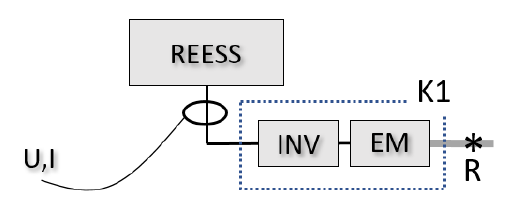
—
그림 16. 사례 6.1.3.1.1., TP1 적용 가능 R에서의 출력 [kW] = (U [V] × I [A] / 1000) × K1
또는,
또는,
6.1.3.1.2
—
6.1.3.1.2. 다음 조건 (a)~(c) 중 적어도 하나가 충족되는 경우:
(a) REESS로부터 전력을 공급받는 각 인버터 입력에서 전류·전압을 결정할 수 있고, 제조사가 각 입력과 해당 기준점(들) 사이 전기 변환 효율을 나타내는 정확한 K1(n) 계수를 제공하는 경우.
(a) REESS로부터 전력을 공급받는 각 인버터 입력에서 전류·전압을 결정할 수 있고, 제조사가 각 입력과 해당 기준점(들) 사이 전기 변환 효율을 나타내는 정확한 K1(n) 계수를 제공하는 경우.
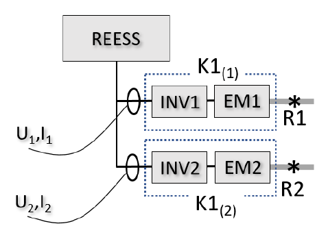
—
그림 17. 사례 6.1.3.1.2.(a) R1에서의 출력 [kW] = (U1 × I1 / 1000) × K1(1) R2에서의 출력 [kW] = (U2 × I2 / 1000) × K1(2) - (b) REESS 출력에서 전류·전압을 결정할 수 있고, 제조사가 REESS와 해당 기준점(들) 사이 인버터·전기기계의 결합 전기 변환 효율을 나타내는 정확한 K1comb 계수를 제공하는 경우.
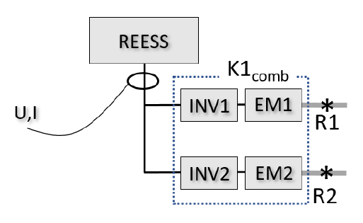
—
그림 18. 사례 6.1.3.1.2.(b) (R1+R2)에서의 출력 [kW] = (U × I / 1000) × K1comb - (c) REESS 출력에서 전류·전압을 결정할 수 있고, 각 인버터 입력과 해당 기준점 사이 전기 변환 효율이 동일하여 동일 K1 계수로 표현되는 경우.
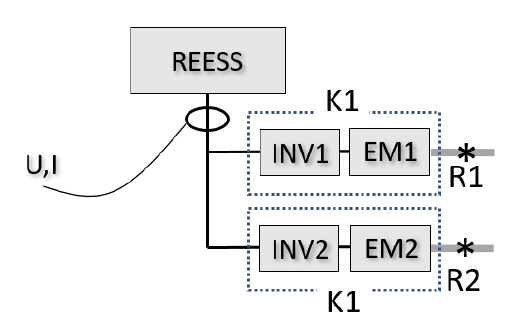
—
그림 19. 사례 6.1.3.1.2.(c) (R1+R2)에서의 출력 [kW] = (U × I / 1000) × K1
6.1.3.2
6.1.3.2. Applicability of TP2: TP2 applicability requires that the power passing through all reference points can be accurately determined; each powered axle is evaluated separately, and TP2 is applicable only if applicable to all powered axles.
6.1.3.2. TP2의 적용성 TP2 적용성은 모든 기준점을 통과하는 출력을 규정 절차 수행으로 정확히 결정할 수 있을 것을 요구한다. 각 구동축을 개별 평가한다. TP2는 모든 구동축에 적용 가능할 때만 적용 가능하다.
이 요건을 전제로, 다음 6.1.3.2.1. 또는 6.1.3.2.2. 중 하나가 충족되면 TP2가 구동축에 일반적으로 적용 가능하다:
이 요건을 전제로, 다음 6.1.3.2.1. 또는 6.1.3.2.2. 중 하나가 충족되면 TP2가 구동축에 일반적으로 적용 가능하다:
6.1.3.2.1
6.1.3.2.1. Where torque to the axle originates from a single reference point and an accurate K2 factor is provided, TP2 is applicable to that axle. Power at R [kW] = (2*pi x torque x rev-per-second / 1000) / K2.
6.1.3.2.1. 하이브리드 전력흐름 기술서가 차축으로의 토크가 단일 기준점에서 비롯되고 그 기준점의 토크가 해당 차축으로만 전달된다고 나타내며, 제조사가 기준점과 측정점 사이 기계 변환 효율을 나타내는 정확한 K2 계수를 제공하는 경우.
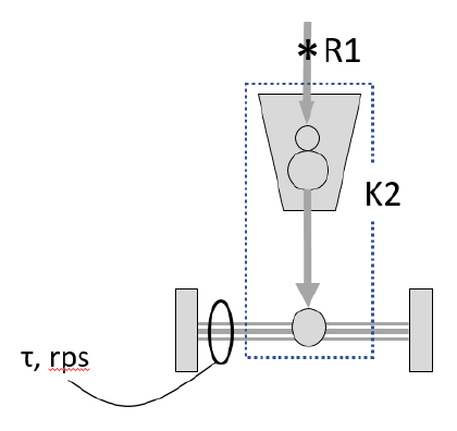
—
그림 20. 사례 6.1.3.2.1., 차축에 TP2 적용 가능. 측정점은 양쪽 차축 대표 R1에서의 출력 [kW] = (2π × τ [Nm] × rps [s⁻¹] / 1000) / K2
또는,
또는,
6.1.3.2.2
6.1.3.2.2. Where the axle torque is a combined torque contributed from a set of reference points routed via the same mechanical path, and an accurate combined K2 is provided, TP2 computes the sum of the power at that set of reference points.
6.1.3.2.2. 하이브리드 전력흐름 기술서가 차축으로의 토크가 기준점 집합으로부터의 토크 기여로 구성된 결합 토크이고, 모든 토크 기여가 그 기준점 집합과 측정점 사이 동일 기계에너지 경로를 통해 해당 차축으로만 전달된다고 나타내며, 제조사가 기준점 집합과 측정점 사이 기계 변환 효율을 나타내는 정확한 K2 계수를 제공하는 경우.
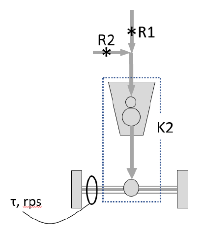
—
그림 21. 사례 6.1.3.2.2., 차축에 TP2 적용 가능 (R1+R2)에서의 출력 [kW] = (2π × τ [Nm] × rps [s⁻¹] / 1000) / K2
둘 이상의 기준점으로부터의 토크 기여가 서로 다른 기계에너지 경로를 통해 차축으로 전달되는 경우(예: [그림 22]) TP2는 그 차축에 적용 불가하다.
둘 이상의 기준점으로부터의 토크 기여가 서로 다른 기계에너지 경로를 통해 차축으로 전달되는 경우(예: [그림 22]) TP2는 그 차축에 적용 불가하다.
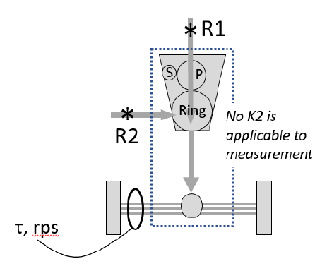
—
그림 22. 차축에 TP2 적용 불가. 가용 측정으로 R1, R2, (R1+R2)를 분해할 수 없음
6.2. 동력계 준비
6.2.1
6.2.1. Rollers (chassis dynamometer only): the chassis dynamometer rollers shall be clean, dry and free of foreign material that could cause slippage.
6.2.1. 롤러(섀시 동력계만 해당): 섀시 동력계 롤러는 청결·건조하고 타이어 슬립을 유발할 이물질이 없어야 한다.
6.2.2
6.2.2. Tire slip (chassis dynamometer only): measures may be taken to stabilize tire slippage that may occur under maximum power, and shall be recorded.
6.2.2. 타이어 슬립(섀시 동력계만 해당): 최대출력 중 발생할 수 있는 타이어 슬립을 안정화하는 조치를 취한다. 이를 위해 차량 내·외에 추가한 중량의 사용·양, 또는 기타 조치의 사용을 기록한다.
6.2.3
6.2.3. Dynamometer warm-up: the dynamometer shall be warmed up per the manufacturer recommendation or other suitable method until internal friction losses stabilize.
6.2.3. 동력계 워밍업: 동력계의 마찰 손실이 안정되도록 동력계 제조사 권고 또는 적절한 방식으로 워밍업한다.
6.2.4
6.2.4. Dynamometer control: during vehicle conditioning the dynamometer may be operated in road-load mode.
6.2.4. 동력계 제어: 차량 컨디셔닝(6.8.3.)에는 동력계를 도로부하 모드 또는 해당 조항이 허용하는 대로 제어한다. 출력 시험(6.8.6.)에는 동력계를 고정속도 모드로 제어한다.
6.3. 차량 준비
—
차량은 양호한 기술 상태로 제시되어야 하며 제조사 권고에 따라 길들이기(run-in)되어야 한다. OVC-HEV·NOVC-HEV는 시험 전 3,000~15,000 km 길들이기·주행되어야 한다. 엔진·변속기·차량은 제조사 권고에 따라 길들이기한다. PEV는 최소 300 km 또는 1회 완전 충전 주행거리 중 더 긴 거리만큼 길들이기되어야 한다. 차량에는 차량 제조사가 원래 장착으로 지정한 종류의 타이어를 장착한다. 타이어는 차량 제조사 권고 또는 사용설명서에 따른 압력으로 팽창시킨다. 슬립 방지용 추가 중량 효과 보정에 필요하면, 차량 제조사가 명시한 코스트다운 시험 질량에서 해당 차축·선정 타이어의 타이어압 범위 하한보다 최대 50%까지 타이어압을 높일 수 있다. 동력계 설정과 모든 후속 시험에 동일 타이어압을 사용한다. 사용한 타이어압을 기록한다. 제조사가 지정한 윤활유·유량을 사용한다. 연료는 ICE 인증에 사용된 것과 동일 연료(장착 시)로 한다. 예컨대 해당 규정으로 인증된 ICE를 장착한 차량에는 UN ECE 규정 제85호에 명시된 연료를 사용한다.
6.4. 측정 장치 준비
—
측정 장치는 차량 내 적절한 위치(들)에 설치한다.
6.5. REESS 초기 충전
—
PEV·OVC-HEV의 경우, 차량 방치(6.6.) 전 또는 중에 REESS를 최대 시스템 출력이 얻어지는 초기 SOC로 충전한다. 제조사는 최대 시스템 출력이 얻어지는 초기 SOC를 명시할 수 있다. REESS 초기 충전은 주변 온도 20 ± 10 ℃에서 수행한다. REESS는 충전 과정이 정상적으로 종료될 때까지 제조사가 명시한 정상 운전 절차에 따라 초기 SOC로 충전한다. SOC는 제조사가 제공한 방법으로 확인한다.
6.6. 차량 방치(soak)
—
차량은 엔진룸 덮개를 열거나 닫은 상태로 방치 구역에서 최소 6시간, 최대 36시간 방치한다. 고전압 배터리 온도 안정화에 필요하면 제조사는 6~36시간 범위 내 특정 방치 시간 또는 범위를 권고할 수 있다. 방치 중 방치 구역 조건은 5.1.4.에 명시된 대로 한다.
6.7. 차량 설치
—
차량은 동력계 제조사 권고 또는 지역·국가 규정에 따라 동력계에 설치한다. 보조장치는 지역 법규가 작동을 요구하지 않는 한 동력계 운전 중 꺼지거나 비활성화되어야 한다. 동력계에서 제대로 작동하는 데 필요하면, 제조사 지침을 사용하여 차량의 동력계 운전 모드를 활성화한다(예: 특정 순서로 스티어링 휠 버튼 사용, 제조사 워크숍 테스터 사용, 퓨즈 제거). 제조사는 담당 기관에 비활성화 장치 목록과 비활성화 정당성을 제공해야 한다. 동력계 운전 모드는 담당 기관의 승인을 받아야 하며 동력계 운전 모드 사용을 기록한다. 차량의 동력계 운전 모드는 시험 조건에서 배출, 연료·에너지 소비, 최대출력에 영향을 주는 어떤 부분의 작동도 활성화·변조·지연·비활성화해서는 안 된다. 동력계 운전에 영향을 주는 모든 장치는 제대로 작동하도록 설정한다. 차량 내 설치된 측정 장치는 적절히 워밍업한다.
6.8. 시험 순서
6.8.1
6.8.1. General: the test shall be carried out in accordance with paragraphs 6.8.3 to 6.8.8 and 6.9 to 6.10. The test shall be stopped immediately if a powertrain warning indicator turns on. Operational metrics shall be monitored and recorded throughout.
6.8.1. 일반 시험은 6.8.3.~6.8.8., 6.9.~6.10.에 따라 수행한다([그림 23] 참조). 파워트레인 관련 경고 표시(들)가 켜지면 즉시 시험을 중단한다. 주: 경고는 예컨대 냉각수 온도·엔진 점검등이다. 다음 운전 지표가 있는 경우 시험 내내 감시·기록한다: (a) 엔진 냉각수 온도, (b) 배터리 온도(가용 시 셀·모듈·팩 온도로 표시), (c) 변속기·기어박스 오일 온도, (d) 배터리 SOC, (e) 전기기계 온도(가용 시 고정자·회전자·냉각유체 온도로 표시). 제조사는 각 운전 지표의 정상 운전 범위를 명시한다.
6.8.2
—
6.8.2. 최대출력 속도 제조사가 최대출력 속도를 제공하지 않았거나 담당 기관이 제공값 검증을 원하면, 부속서 2에 기술된 절차로 최대출력 속도를 결정한다.
6.8.3
6.8.3. Vehicle conditioning: operate the vehicle until the manufacturer-specified normal operating temperature ranges are reached and stabilized. Initial conditioning is performed in power-rating mode at 60 km/h at the vehicle road load for at least 20 minutes, or as recommended by the manufacturer.
6.8.3. 차량 컨디셔닝 측정 장치가 데이터 수집을 시작한다. 컨디셔닝의 목적은, 온도 관련 운전 지표(6.8.1.)에 대해 제조사가 명시한 정상 운전 온도 범위(6.1.1.4.)에 도달하여 안정될 때까지 차량을 운전하는 것이다. 시험 전, 해당되면 차량을 출력정격 모드에 두고(6.8.5. 참조) 차량 도로부하에서 60 km/h로 최소 20분간, 또는 차량 제조사 권고대로 주행하여 초기 컨디셔닝을 수행한다. 차량 제조사 또는 담당 기관은 안정 운전 지표 달성에 필요하면 다른 시간·속도·운전자 선택 모드·동력계 모드·사이클을 명시할 수 있다. 초기 차량 컨디셔닝 종료 시 운전 지표(6.8.1. 참조)를 기록한다. 시험 중에는 운전 지표를 감시하고 정상 운전 온도 범위 내로 유지하는 데 필요한 추가 컨디셔닝을 수행한다.
6.8.4
—
6.8.4. REESS 조정 6.8.3.에 따른 차량 컨디셔닝 중 SOC를 감시한다. 차량 컨디셔닝 종료 시 SOC를, 제조사가 권고한 최대 시스템 출력이 얻어지는 SOC로 조정한다. REESS 조정은 6.8.7.에 따른 출력 시험 반복에도 적용된다. REESS 조정은, 동력계를 고정속도 모드로 운전하면서 경회생제동을 사용하거나 차량을 타력주행시키거나, 제조사 권고대로 수행할 수 있다. 어느 방법이든 충전율을 감시하고, 배터리 과열이나 배터리 출력 디레이팅을 피하도록 제조사 권고대로 제한한다.
6.8.5
6.8.5. Vehicle operation: for vehicles with driver-selectable modes, select the mode for which a vehicle system power rating is desired and record it as the power-rating mode; place the dynamometer in fixed speed mode set to the speed of maximum power and allow it to stabilize.
6.8.5. 차량 운전 운전자 선택 모드가 있는 차량은, 본 절차로 결정되는 차량 시스템 출력 정격이 시험 중 활성화된 모드에 따라 달라질 수 있다. 차량 시스템 출력 정격을 구하고자 하는 모드를 선택한다. 선택한 모드를 출력정격 모드로 기록한다. 동력계를 고정속도 모드에 둔다. 동력계 고정속도를 최대출력 속도로 설정하고 속도가 안정되도록 한다.
6.8.6
6.8.6. Power test: the maximum accelerator pedal command shall be given by pedal position or vehicle communication network for at least 10 seconds, as rapidly as possible; the gear shall be selected as recommended by the manufacturer for a typical driver to achieve maximum power.
6.8.6. 출력 시험 최대 가속페달 지령을 페달 위치 또는 차량 통신 네트워크로 최소 10초간 준다. 최대 가속 지령은 가능한 한 신속히 준다. 최대 출력 전달을 끌어내는 데 필요하면, 최대 가속페달 지령 전에 제조사 권고대로 가속페달 지령을 변화시키는 것이 허용된다(예: 킥다운 상태 달성에 필요한지 제조사에 문의). 기어박스에 운전자 선택 기어가 있으면, 최대출력 달성을 위해 일반 운전자에게 권고되는 대로 기어를 선택한다. 일반 운전자가 사용할 수 없는 특수 모드·동작을 통한 기어 변속은 허용되지 않는다.
6.8.7
6.8.7. Repetition of the power test: the power test shall be repeated for a total of five repetitions; prior to the second and subsequent repetitions the REESS shall be adjusted.
6.8.7. 출력 시험 반복 6.8.6.의 출력 시험을 [그림 23]과 같이 총 5회 반복한다. 2회차 및 이후 반복 전에 6.8.4.에 따라 REESS를 조정한다. 6.8.1.에 열거된 온도 관련 운전 지표를 모든 반복 중 감시하고, 각 반복 중 제조사가 명시한 정상 운전 범위 내에 머무는지 확인한다. 필요하면 반복 사이에 6.8.3.에 따라 차량을 재컨디셔닝한다.
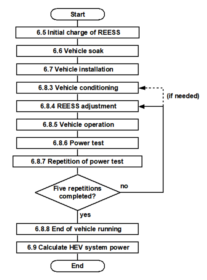
—
그림 23. 시험 순서 — 6.5 초기충전 → 6.6 방치 → 6.7 설치 → 6.8.3 컨디셔닝 → 6.8.4 REESS 조정 → 6.8.5 운전 → 6.8.6 출력시험 → 6.8.7 반복(5회 완료?) → 6.8.8 종료 → 6.9 계산
6.8.8
6.8.8. End of vehicle running: at the end of vehicle running the operational metrics shall be recorded, and the vehicle and measurement devices shall be stopped.
6.8.8. 차량 주행 종료 차량 주행 종료 시 운전 지표(6.8.1. 참조)를 기록한다. 측정 완료 후 차량과 측정 장치를 정지한다.
6.9. 차량 시스템 출력 정격의 계산
6.9.1
6.9.1. General: for each of the 2nd, 3rd, 4th and 5th repetitions, the time-series data shall be analysed to calculate peak (3.5.9) and sustained (3.5.10) vehicle system power; the rating is the mean of the four repetitions, and each individual value should be within plus or minus 5% of the mean.
6.9.1. 일반 6.8.7.에 따른 2~5회차 반복 각각에 대해, 6.8에서 얻은 시계열 데이터를 분석하여 차량 시스템 출력을 계산한다. 각 반복에 대해 두 가지 출력 계산을 수행한다: - (a) 피크 차량 시스템 출력: 10초 측정 시간에 적용한 2초 이동평균 필터의 최댓값인 2초 “피크” 출력; 그리고 - (b) 지속 차량 시스템 출력: 8초~10초 측정 시간 구간 내 평균 출력을 정의하는 “지속” 출력.
계산 목적상, 10초 측정 시간 구간은 가속페달 지령 측정으로 표시되는 가속페달 지령이 최대에 도달하고, (변경된 경우) 기어비가 최소 10초간 일정한 구간을 시작했을 때 시작된다. 차량 설계가 최대출력 조건에서 10초 내내 안정 기어비를 달성하지 못하면, 담당 기관 승인을 받아 제조사 권고에 따라 시간 구간을 시작할 수 있다.
마지막으로, 분석한 4회 반복의 각 결과의 평균으로 차량의 피크·지속 시스템 출력 정격을 계산한다. 분석한 4회 반복 각각의 변동을 그 평균에 대한 백분율로 계산하고 기록한다. 개별 값의 최대 변동은 평균의 ±5%를 넘지 않아야 한다. 변동이 너무 크면 동력계 설정·차량 구성을 점검하고, 가능한 원인을 제조사와 협의하고, 반복을 다시 수행한다. 변동을 줄일 수 없으면 시스템 출력 정격은 담당 기관의 승인 대상이 된다.
6.9.2
—
6.9.2. TP1 계산 차량 시스템 출력은 각 기준점 출력의 합으로 계산한다:
차량 시스템 출력 [kW] = Σ Ri (i=1 부터 n 까지)
여기서 n = 출력 결정 기준점의 수, Ri = i번째 기준점의 출력 [kW]
각 Ri의 출력은 6.9.2.1.~6.9.2.3.에 따라 결정한다.
차량 시스템 출력 [kW] = Σ Ri (i=1 부터 n 까지)
여기서 n = 출력 결정 기준점의 수, Ri = i번째 기준점의 출력 [kW]
각 Ri의 출력은 6.9.2.1.~6.9.2.3.에 따라 결정한다.
6.9.2.1
6.9.2.1. For reference points consisting of ICE power: first determine the ICE power from the full-load power curve as a function of engine speed, subject to confirmation of intake manifold pressure and fuel flow rate (use the curve value if both are within 5% of the certification values; otherwise re-test under the observed conditions).
6.9.2.1. ICE 출력으로 구성되는 기준점: 먼저, 차량에 장착된 엔진에 적용되는 엔진 회전수 함수로서의 전부하 출력곡선을 참조하고, 흡기 매니폴드 압력·연료 유량의 확인을 조건으로 ICE 출력을 결정한다. 전부하 출력곡선은 적용 엔진 시험 표준에서 도출하며 정상상태 조건에서 측정한다. ISO 1585 또는 UN 규정 제85호에 의한 엔진 인증이 규정상 적용되는 제조사의 경우, 적용 엔진 시험 표준은 각각 ISO 1585:1992 또는 UN 규정 제85호이다. 다른 제조사의 경우, 적용 표준은 지역·국가 규정으로 적용되는 것이다. 규정상 적용되는 엔진 시험 표준이 없는 경우, 적용 표준은 SAE J1349(정상상태)이다. 엔진 동력계 시험 연료는 적용 표준에 명시된 대로 한다.
흡기 매니폴드 압력·연료 유량을 확인하려면, 측정값을 측정 엔진 회전수에서 적용 표준의 인증 결과 보고값과 비교한다.
다음이면: > |(측정 연료 유량 − 인증 시 연료 유량)| < (0.02) × (인증 시 연료 유량) > 그리고 > |(시험 시 게이지 압력 − 인증 시 게이지 압력)| < (0.02) × (인증 시 흡기 매니폴드 압력)
Ri는 측정 엔진 회전수에서 전부하 출력곡선이 나타내는 출력이다. 그렇지 않으면, 위에서 측정한 엔진 회전수·흡기 매니폴드 압력·연료 유량을 사용하여 관측 조건에서 ISO 1585:1992 또는 UN 규정 제85호(해당되는 것)를 수행하여 Ri를 결정하거나, 관측 조건에서의 ICE 출력 결정을 차량 제조사에 지원 요청한다. 주: Ri의 어느 일부가 REESS 충전으로 전달되면, REESS로 들어가는 전기출력을 6.9.2.2.에 따라 음(−)의 출력으로 계산한다.
6.9.2.2
6.9.2.2. For reference points consisting of electric machine power where the measurement point is the REESS output: Ri [kW] = (U_REESS x I_REESS / 1000 - P_DCDC - P_aux) x K1, where P_DCDC is power to the DC/DC converter for 12 V auxiliaries (1.0 kW or measured) and P_aux is power to high-voltage auxiliaries other than P_DCDC.
6.9.2.2. 전기기계 출력으로 구성되고 측정점이 REESS 출력인 기준점: Ri는 다음 식으로 결정한다:
Ri [kW] = ( (U_REESS × I_REESS)/1000 − P_DCDC − P_aux ) × K1
U_REESS: 측정 REESS 전압 [V]
I_REESS: 측정 REESS 전류 [A] (REESS로 흘러 들어가면 음)
P_DCDC: 12V 보조용 DC/DC 컨버터로의 출력(있는 경우, 1.0 kW 또는 측정값) [kW]
P_aux: P_DCDC 외에 REESS로부터 전력을 공급받는 고전압 보조장치로의 출력(있고 시험 중 작동 시, 측정 또는 추정값) [kW]. 추정 시 제조사는 추정값을 뒷받침하는 증거를 제공해야 하며, 추정값 사용은 담당 기관 승인 대상.
K1: 6.1.1.2.·6.1.3.1.에 기술된, DC 전기출력에서 기계출력으로의 변환계수.
K1이 기준점 집합 출력의 합(예: [그림 18]의 (R1+R2))으로의 변환을 나타내면, 이 식은 기준점 집합 출력의 합을 계산한다. P_DCDC와 P_aux를 측정하는 경우: > P_DCDC [kW] = (U_DCDC × I_DCDC) / 1000 > P_aux [kW] = (U_aux × I_aux) / 1000 (각 해당 보조장치에 대해)
6.9.2.3
6.9.2.3. For reference points consisting of electric machine power where the measurement point is the inverter input: Ri [kW] = (U_input x I_input / 1000) x K1.
6.9.2.3. 전기기계 출력으로 구성되고 측정점이 인버터 입력인 기준점: Ri는 다음 식으로 결정한다:
Ri [kW] = ( (U_Input × I_Input)/1000 ) × K1
U_Input: 인버터 입력의 측정 DC 전압 [V]
I_Input: 인버터 입력의 측정 전류 [A]
K1: 6.1.1.2.·6.1.3.1.에 기술된 변환계수.
K1이 기준점 집합 출력의 합(예: 인버터가 전기기계 집합에 전력 공급)으로의 변환을 나타내면, 이 식은 기준점 집합 출력의 합을 계산한다.
Ri [kW] = ( (U_Input × I_Input)/1000 ) × K1
U_Input: 인버터 입력의 측정 DC 전압 [V]
I_Input: 인버터 입력의 측정 전류 [A]
K1: 6.1.1.2.·6.1.3.1.에 기술된 변환계수.
K1이 기준점 집합 출력의 합(예: 인버터가 전기기계 집합에 전력 공급)으로의 변환을 나타내면, 이 식은 기준점 집합 출력의 합을 계산한다.
6.9.3
—
6.9.3. TP2 계산
6.9.3.1
6.9.3.1. Calculation for TP2: the vehicle system power is the sum of the power at each reference point. Ri = P_axle / K2, where P_axle [kW] = (2 x pi x axle speed[rev/s] x axle torque[Nm]) / 1000.
6.9.3.1. 계산 차량 시스템 출력은 각 기준점 출력의 합으로 계산한다: > 차량 시스템 출력 [kW] = Σ Ri (i=1 부터 n 까지)
각 기준점 출력은 다음과 같이 계산한다: > Ri [kW] = ( P_axle / K2 ) > > 여기서 P_axle = 해당 구동축에서 측정한 출력 [kW]: > P_axle [kW] = (2π × 차축 또는 휠 속도 [rev·s⁻¹] × 차축 또는 휠 토크 [Nm]) / 1000 > > K2 = 6.1.1.2.·6.1.3.2.에 기술된, 차축에 적용되는 기계에너지 변환 효율계수.
K2가 기준점 집합 출력의 합(예: [그림 21]의 (R1+R2))으로의 변환을 나타내면, 이 식은 기준점 집합 출력의 합을 계산한다.
각 기준점 출력은 다음과 같이 계산한다: > Ri [kW] = ( P_axle / K2 ) > > 여기서 P_axle = 해당 구동축에서 측정한 출력 [kW]: > P_axle [kW] = (2π × 차축 또는 휠 속도 [rev·s⁻¹] × 차축 또는 휠 토크 [Nm]) / 1000 > > K2 = 6.1.1.2.·6.1.3.2.에 기술된, 차축에 적용되는 기계에너지 변환 효율계수.
K2가 기준점 집합 출력의 합(예: [그림 21]의 (R1+R2))으로의 변환을 나타내면, 이 식은 기준점 집합 출력의 합을 계산한다.
6.9.3.2
—
6.9.3.2. ICE 출력 보정 차량 시스템 출력 정격의 ICE 출력 부분은, 다음을 충족할 수 없는 경우 ISO 1585:1992 6절 규정에 따라 보정한다: - ISO 1585:1992 6.2.1절의 기준 대기·온도 조건; 또는 - ISO 1585:1992 6.3절에 따른 자동 제어 조건.
주: 6.9.2.1.에 따른 적용 표준이 ISO 1585가 아닌 경우(예: UN 규정 제85호), ICE 출력 보정은 적용 표준의 동등 부분(예: UN 규정 제85호 5절)에 따라 수행한다. ICE 출력 부분 보정이 필요하면 6.9.3.3.을 따르고, 그렇지 않으면 6.10.으로 계속한다.
주: 6.9.2.1.에 따른 적용 표준이 ISO 1585가 아닌 경우(예: UN 규정 제85호), ICE 출력 보정은 적용 표준의 동등 부분(예: UN 규정 제85호 5절)에 따라 수행한다. ICE 출력 부분 보정이 필요하면 6.9.3.3.을 따르고, 그렇지 않으면 6.10.으로 계속한다.
6.9.3.3
6.9.3.3. Corrected vehicle system power rating for TP2: where TP2 does not deliver a distinct ICE power portion (e.g. power-split), derive PICE by subtracting the non-ICE reference points (measured by TP1) from the summed power, correct PICE per ISO 1585:2020 paragraph 6, and recompute the system power as the corrected ICE power plus the non-ICE reference point power.
6.9.3.3. TP2의 보정된 차량 시스템 출력 정격 ICE 출력 보정에는 차량 시스템 출력 정격 중 ICE 출력 부분(PICE)의 별개 값이 필요하다. 많은 파워트레인 구조에서 TP2는 ICE 출력 부분의 별개 값을 제공하지 않는다. 예컨대 [그림 24]는 TP2가 차축 측정 출력에 K2를 적용하여 각각의 별개 값 대신 R1(PICE)과 R2(P_non-ICE)의 합을 제공하는 파워트레인을 보여준다.
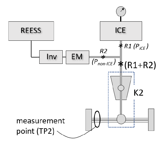
—
그림 24. TP2가 ICE 출력(R1)의 별개 값을 제공하지 않는 파워트레인 예시
TP2가 PICE의 별개 값을 제공하지 않으면, 아래 (a)~(c)를 수행하여 ICE 기준점과 합산된 비ICE 기준점의 출력을 차감함으로써 PICE를 도출한다. 그렇지 않으면 (d)로 진행한다. - (a) ICE 기준점을 포함하는 합산 기준점 집합과 TP2가 제공한 그 합산 출력(P_summed)을 식별한다. - (b) TP1을 수행하여 집합 내 각 비ICE 기준점 출력을 결정하고, 이를 합하여 비ICE 부분(P_summed,non-ICE)을 구한다. - (c) 합산 출력(P_summed)에서 비ICE 기준점 출력(P_summed,non-ICE)을 차감한다. 그 결과가 측정 ICE 출력 PICE이다: > PICE [kW] = P_summed [kW] − P_summed,non-ICE [kW] - (d) 측정 ICE 출력을 ISO 1585:1992(또는 6.9.2.1.에 따라 다른 적용 표준)에 따라 보정한다: > PICE,corrected [kW] = PICE [kW] × (출력 보정계수) > (출력 보정계수는 ISO 1585:1992 6절, 또는 다른 적용 표준의 동등 부분에 따름) - (e) 보정된 ICE 출력과 파워트레인 내 모든 비ICE 기준점 출력의 합으로 보정된 차량 시스템 출력 정격을 계산한다: > 차량 시스템 출력_corrected [kW] = (Σ R_all non-ICE [kW]) + PICE,corrected [kW]
주: 차량 제어 시스템이 고도·기온에 따른 ICE 출력 변동을 전기적으로 보상하기 위해 전기기계 출력을 조정하는지 제조사에 문의한다. 이 경우 출력 보정 수행 후 그 전기 보상량을 차량 시스템 출력 정격에서 차감한다.
6.10. 차량 시스템 출력 정격의 내부 검증
—
TP1 또는 TP2에 따른 차량 시스템 출력 정격은 다음 요건을 충족해야 한다: 기준점(들)과 노면 사이의 함축 하류 효율은 1을 초과해서는 안 된다. 함축 하류 효율은, 8초~10초 사이 동력계 롤러(해당 시 허브 동력계)에서 기록된 평균 출력을 (6.9.3.3.에 따른 보정 전) 지속 차량 시스템 출력 결과로 나누어 계산한다.
부속서 1 — 출력 결정 기준점의 식별
1. 일반 접근
1.1
1.1. Both TP1 and TP2 transform a specified set of vehicle test measurements into a system power rating referenced to one or more power determination reference points.
1.1. TP1·TP2 모두 지정된 차량 시험 측정값 집합을, 하나 이상의 출력 결정 기준점을 통과하여 전달되는 기계적 출력을 나타내는 차량 시스템 출력 정격으로 변환한다.
1.2
1.2. The power determination reference point is the point in the electrified powertrain closest to the engine output shaft of a conventional vehicle.
1.2. 출력 결정 기준점은, 종래 차량의 엔진 출력축에 가장 가까운, 전동화 파워트레인 기계적 전력흐름 경로 상의 점을 나타내기 위한 것이다. 여기서 “가깝다”는 것은, 바퀴를 구동하는 기계적 출력이 저장된 에너지로부터 처음 생성되는 파워트레인 상의 점을 의미한다. 이는 종래 차량이 엔진 출력축 하류에서 발생하는 출력 손실을 고려하지 않고 엔진 정격출력과 같은 시스템 출력 정격을 부여받는 전통과 부합한다.
1.3
1.3. The power determination reference point is defined in paragraph 3.5 as the point in the mechanical power flow path where the mechanical energy that drives the wheels is first produced.
1.3. 출력 결정 기준점은 3.5.에 정의된 전동화 파워트레인 기계적 전력흐름 경로 상의 한 점이다. 가장 일반적 의미에서 기준점은, 최대출력 조건에서 바퀴를 구동하는 기계적 출력이 에너지 저장 시스템으로부터 처음 생성되는 곳을 나타낸다. 주어진 전동화 파워트레인은 구동축(들)으로 가는 모든 추진 출력원을 반영하는 데 필요한 만큼 하나 이상의 출력 결정 기준점을 가질 수 있다. 차량 시스템 출력 정격은 모든 기준점을 통과하여 전달되는 출력의 합이다.
1.4
1.4. For complex electrified powertrains, the reference points may depend on the given operating mode or the given power rating sought for the vehicle.
1.4. 복잡한 전동화 파워트레인의 기준점은, 차량의 주어진 운전 모드나 주어진 출력 요구에서 활성화되는 구체적 전력흐름 경로에 따라 달라질 수 있다. 본 GTR의 시스템 출력 결정 목적상, 기준점은 본 부속서의 요건에 따라 식별한다.
1.5
—
1.5. TP1·TP2 모두에서 차량 시스템 출력 정격 계산은, 최대출력 조건에서 식별된 모든 기준점 출력의 합 추정치를 산출해야 한다. TP1·TP2 중 무엇을 적용하든 주어진 파워트레인에는 동일 기준점이 적용되어야 한다.
2. 출력 결정 기준점의 식별
2.1. 일반 고려사항
2.1.1
2.1.1. The power determination reference points capture the total mechanical power delivered to the road under the maximum power condition.
2.1.1. 출력 결정 기준점은 최대출력 조건에서 노면으로 전달되는 총 기계적 출력의 모든 원천을 나타낸다. 즉, 파워트레인 구조 배치뿐 아니라 최대출력 조건에서의 파워트레인 상태와 적용 운전 모드에도 근거한다. 이 상태에서 작동하지 않거나 노면에 추진 에너지를 기여하지 않는 추진 에너지 변환장치는 포함되지 않는다.
2.2. 병렬 구조
2.2.1
2.2.1. For a parallel architecture (example in Figure 25), the reference points are generally (a) R1 at the engine and (b) R2 at the electric machine.
2.2.1. 병렬 구조([그림 25] 예시)의 출력 결정 기준점은 일반적으로 (a) 엔진 기계적 출력축과 (b) 노면에 기계적 출력을 제공하는 모든 전기기계의 기계적 출력축(들)이다. 차량 시스템 출력 정격은 기준점을 통과하는 출력의 합이다.
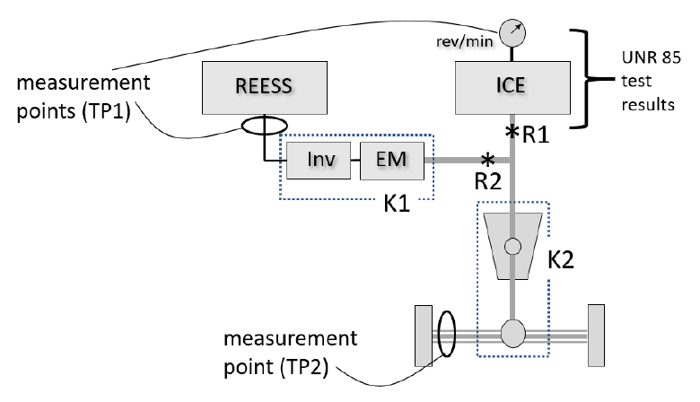
—
그림 25. 단순 병렬 구조의 기준점 R1·R2 예시. TP2 측정점은 양쪽 차축 대표
2.2.2
2.2.2. In Figure 25 the electric machine EM drives the engine output shaft directly; the reference points are R1 and R2.
2.2.2. [그림 25]에서 전기기계 EM은 엔진 출력축을 직접 구동한다. 기준점은 R1과 R2이다. 2.2.3. 여기서 TP1은 엔진 회전수·매니폴드 압력·연료 유량을 측정(전부하 출력곡선 참조)해 R1 출력을, REESS 전류·전압을 측정(K1으로 보정)해 R2 출력을 결정함으로써 수행할 수 있다. 2.2.4. TP2는 구동 바퀴 또는 차축 허브에서 토크·속도를 측정(K2로 보정)해 R1+R2 합을 결정함으로써 수행할 수 있다.
2.3. 동력분기 구조
2.3.1
2.3.1. A power-split architecture (example in Figure 26) often uses one or more planetary gear sets; the reference points are R1 and R2REESS.
2.3.1. 동력분기 구조([그림 26] 예시)는 흔히 하나 이상의 유성기어 세트를 포함하는 복잡한 기어박스에 둘 이상의 입출력을 가지며, ICE 출력과 REESS 출력을 혼합하는 직렬 동력변환 경로를 포함할 수도 있다. 이런 구조의 출력 결정 기준점은 일반적으로 (a) 엔진 기계적 출력축과 (b) 노면에 기계적 출력을 제공하는 모든 전기기계의 기계적 출력축(들)이다. (b)와 관련해, 전기기계가 전달하는 기계적 출력이 ICE에서 비롯된 출력을 포함하는 경우, REESS에서 비롯된 부분만 계산한다([그림 26]의 R2REESS). 차량 시스템 출력 정격은 R1과 R2REESS를 통과하는 출력의 합이다.
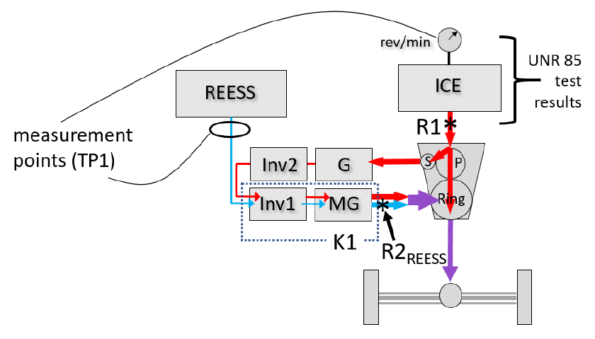
—
그림 26. 단순 동력분기 구조의 기준점 R1·R2REESS 예시
2.3.2
2.3.2. Here TP1 determines R1 from engine speed, manifold pressure and fuel flow (full-load power curve) and R2REESS from the REESS measurement with K1. (TP2 is not applicable.)
2.3.2. 여기서 TP1은 엔진 회전수·매니폴드 압력·연료 유량 측정(전부하 출력곡선 참조)으로 R1 출력을, REESS 전류·전압 측정(K1으로 보정)으로 R2REESS 출력을 결정함으로써 수행할 수 있다. K1은 (직렬 경로와 REESS의) 묘사된 모든 출력을 전달할 때 Inv1+MG 조합의 순효율을 나타내도록 선택해야 한다. 2.3.3. 6.1.3.2.의 적용성 지침이 나타내듯, 차축에 도착하는 출력이 서로 다른 변환 효율을 겪는 전력흐름의 결합이어서 단일 차축 출력 측정으로 R1과 R2REESS 출력을 재구성하기가 비현실적이므로 TP2는 적용 불가하다.
2.4. 순수 직렬 구조
2.4.1
2.4.1. A pure series architecture (example in Figure 27) has no mechanical connection between the engine and the road; the reference points are R1 and R2REESS.
2.4.1. 순수 직렬 구조([그림 27] 예시)는 엔진과 노면 사이 기계적 연결 없이 하나 이상의 전기 변환 경로에 전력을 공급하는 ICE를 포함한다. 출력 결정 기준점은 일반적으로 (a) 엔진 기계적 출력축과 (b) 노면에 기계적 출력을 제공하는 모든 전기기계의 기계적 출력축(들)이다. (b)와 관련해, 전기기계가 전달하는 기계적 출력이 ICE에서 비롯된 출력을 포함하는 경우, REESS에서 비롯된 부분만 계산한다(R2REESS). 차량 시스템 출력 정격은 R1과 R2REESS를 통과하는 출력의 합이다.
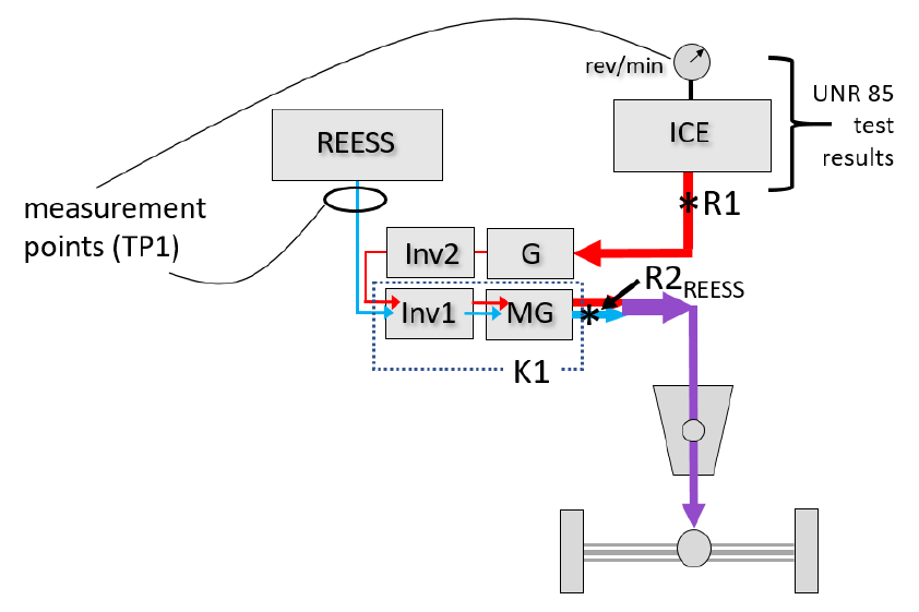
—
그림 27. 순수 직렬 구조의 기준점 예시
2.4.2
2.4.2. TP1 is performed as in 2.3.2. (TP2 is not applicable to a pure series architecture.)
2.4.2. (TP1 수행 방식은 2.3.2.와 동일.) 2.4.3. (TP2 적용 불가 사유는 2.3.3.과 동일.)
2.5. 둘 이상의 구동축을 가진 구조
2.5.1
2.5.1. Where two or more axles drive the vehicle under the maximum power condition, both axles are tested simultaneously.
2.5.1. 최대출력 조건에서 둘 이상의 차축이 차량을 구동하면, 양 차축을 동시에 시험해야 한다. 각 차축이 동일한 추진 에너지 변환장치 집합으로 구동되지 않으면, 흔히 특정 차축에 연관된 기준점이 존재한다. [그림 28]이 예시이다. R1·R2 출력은 한 차축에, R3 출력은 다른 차축에 전달된다. 차량 시스템 출력 정격은 R1·R2·R3를 통과하는 출력의 합이다.
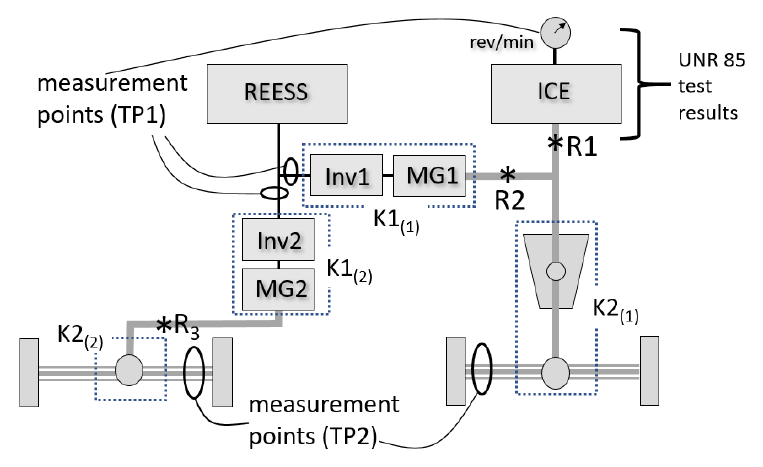
—
그림 28. 서로 다른 기준점을 통해 각각 출력을 받는 둘 이상의 구동축 구조 예시
2.5.2
2.5.2. Here TP1 determines R1 from engine measurements and the electric-machine reference points from the inverter inputs with the applicable K1 factors.
2.5.2. 여기서 TP1은 엔진 회전수·매니폴드 압력·연료 유량 측정으로 R1 출력을, Inv1·Inv2 입력에서 전류·전압 측정(각각 K1(1)·K1(2)로 보정)으로 R2·R3 출력을 결정함으로써 수행할 수 있다(대안으로 6.1.3.1. 조건 하에 인버터 대신 REESS 계측이 적용될 수 있음). 2.5.3. TP2는 우측 차축의 토크·속도 측정(K2(1)로 보정)으로 R1+R2 합을, 좌측 차축의 토크·속도 측정(K2(2)로 보정)으로 R3를 결정함으로써 수행할 수 있다.
2.6. 기타 구조
2.6.1
2.6.1. For other architectures or variants not listed in this annex, the reference points and the applicability of TP1 or TP2 shall be determined by the manufacturer and the responsible authority.
2.6.1. 본 부속서에 열거되지 않은 다른 구조 또는 열거된 구조의 변형에 대한 기준점은, 3.5.의 출력 결정 기준점 정의에 부합하고 본 부속서에서 논의된 원칙·지침과 일관된 방식으로 선정해야 한다. 출력 결정 기준점 선정은 담당 기관의 승인 대상이다.
부속서 2 — 최대출력 속도의 결정
1
1. The speed of maximum power (defined in paragraph 3.5) is the speed at the maximum of the power-speed relationship (see Figure 29).
1. 최대출력 속도(3.5. 정의)는 출력-속도 관계([그림 29] 참조)에서의 최댓값으로, 여기서 출력은 동력계에 전달되는 출력이고 속도는 동력계에서 고정속도 모드로 운전되는 차량의 속도이다.
2
2. The speed of maximum power is determined by the manufacturer or the responsible authority by the procedure described in this annex.
2. 최대출력 속도는 제조사 또는 담당 기관이 본 부속서에 기술된 절차로 결정한다.
3
3. The speed of maximum power is identified by operating the vehicle at a series of fixed dynamometer speeds (operating points) to find the speed at which power is greatest.
3. 최대출력 속도는, 최대출력이 발생하는 속도를 식별하기 위해 일련의 운전점(고정 차량 속도)에서 [그림 30]에 묘사된 시험 순서를 수행하여 식별한다.
4
4. The series of operating points shall be spaced closely enough to identify the speed of maximum power with sufficient confidence.
4. 일련의 운전점은 최대출력 속도를 충분한 신뢰로 식별할 만큼 촘촘히 간격을 둔다. 처음에는 거친 분해능으로 속도 범위를 포괄하도록 운전점을 선택한 뒤, 피크 출력이 얻어지는 속도를 식별하기 위해 더 미세한 분해능으로 진행할 수 있다.
5
5. At each operating point, the power delivered to the dynamometer is determined from dynamometer power data when available, or from measured torque and speed.
5. 각 운전점에서 동력계에 전달되는 출력은, 가용 시 동력계 출력 데이터 또는 동력계 속도·토크 데이터를 참조해 결정할 수 있다.
6
6. The determined speed of maximum power is reported as an integer in kilometres per hour (km/h).
6. 결정된 최대출력 속도는 시속 킬로미터(km/h) 단위의 정수로 보고한다.
7
7. Where the vehicle manufacturer has specified the speed of maximum power and verification is desired, test at points above and below the specified speed.
7. 차량 제조사가 최대출력 속도를 명시했고 검증이 필요하면, 명시 속도 위·아래로 약간 다른 속도에서 주행하여 명시 속도에 피크가 존재함을 확인한다.
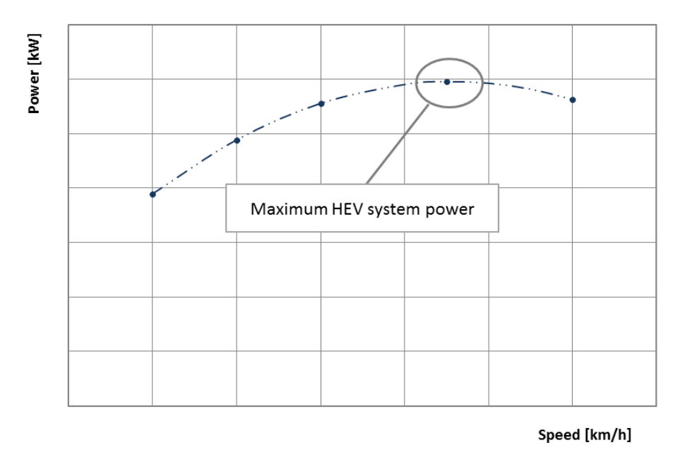
—
그림 29. 출력-속도 관계 — 최대 HEV 시스템 출력 지점
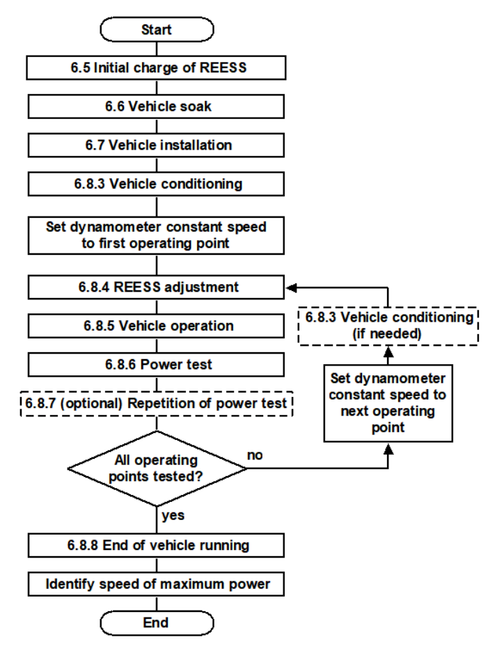
—
그림 30. 최대출력 속도 결정을 위한 시험 순서
부속서 3 — [유보] 방법 동등성의 결정
—
[RESERVED: Annex 3 — Determination of method equivalency] (현 버전에서는 유보 상태이며 내용 없음.)
번역 후기 (실무 참고)
—
R177과의 관계: 본 GTR 21의 “II. 규정 본문 + 부속서 1·2”가 사실상 UN R177의 시험 절차 본문으로 전환(transposition)되었습니다. R177e.pdf와 대조하면 거의 동일한 조항 구조를 확인하실 수 있습니다. 다만 R177에는 형식승인·상호인정 관련 행정 조항이 추가되고, GTR 21의 “I. 기술적 근거” 파트(제정 경위·검증 이력)는 포함되지 않습니다.
핵심 수치 앵커: 시험실 25 ℃(±10 ℃), 대기압 80~110 kPa, 가속페달 최소 10초 전개, 5회 반복·마지막 4회 평균, 변동 한계 평균의 ±5%, K1 기본 개념(전기변환효율)·K2(기계변환효율), 내부 검증 시 함축 하류효율 ≤ 1.
적용 범위 주의: 연료전지차 제외(2.2.). 카테고리·질량 기준(3,500 kg)과 “최대출력 조건에서 전기기계가 구동 기여”라는 HEV 조건(2.1.(c))을 국내 차종 분류와 대조 필요.
번역 한계: 그림(파워트레인 도식·곡선)은 원문 PDF를 함께 보셔야 의미가 완전합니다. 수식은 원문 기호를 우리말 변수명과 병기해 옮겼으나, 공식 인용·고시 반영 시 원문 수식을 그대로 확인하시기 바랍니다.