규정 이해 · 원문·번역 전체 대역
UN R177 원문 (번역본)
영문 원문 전체 ↔ 한글 번역을 조항별로 빠짐없이. 제1조~제15조 + 부속서, 그림 포함.
📄 원문(UNECE) 열기 ↗
E/ECE/TRANS/505/Rev.3/Add.176
⚠️ 한글은 AI 번역(연구 참고용)이며 정본은 영문 원문입니다. R177 자체 PDF 그림은 본 환경에서 추출 불가하여, 동일 도식인 UN GTR 21의 그림을 해당 위치에 삽입했습니다(R177은 GTR 21을 1958협정으로 옮긴 규정으로 도식 동일).
조항
원문 (English)
번역 (한글)
1. Scope and application — 적용 범위
1.1
This Regulation applies to vehicles that meet all of the following criteria (a), (b) and (c): (a) Are hybrid electric vehicles, or are pure electric vehicles that have more than one propulsion energy converter; (b) Are classified in category N1, or are classified in category M and have a technically permissible maximum laden mass not exceeding 3,500 kg; (c) If a hybrid electric vehicle, at least one electric machine contributes to propulsion under the maximum power condition.
이 규정은 다음 (a)·(b)·(c)를 모두 충족하는 차량에 적용된다: (a) HEV이거나 추진 에너지변환기를 2개 이상 가진 PEV; (b) N1류, 또는 최대적재중량 3,500kg 이하의 M류; (c) HEV의 경우 최대출력 조건에서 최소 1개의 전동기가 구동에 기여.
1.2
This Regulation does not apply to fuel cell vehicles.
이 규정은 연료전지차(FCV)에는 적용하지 않는다.
1.3
When determined according to the requirements of this Regulation, the resulting vehicle system power rating may be considered as comparable to the power rating traditionally assigned to conventional vehicles, which is the power rating of the internal combustion engine.
이 규정에 따라 결정된 차량 시스템 출력 정격은, 종래 차량의 출력 정격(내연기관 출력 정격)과 비교 가능한 것으로 간주될 수 있다.
2. Abbreviations — 약어
2
AWD (all-wheel drive), FSD (full scale deflection), HEV, ICE, ICEV, ISO, NOVC-HEV, OVC-HEV, PEV, REESS, SOC, TP1, TP2, UN.
AWD(전륜구동), FSD(최대눈금편향), HEV(하이브리드 전기차), ICE(내연기관), ICEV(내연기관차), ISO, NOVC-HEV(비외부충전형 HEV), OVC-HEV(외부충전형 HEV), PEV(순수전기차), REESS(재충전식 전기에너지 저장장치), SOC(충전상태), TP1·TP2(시험절차 1·2), UN.
3. Definitions — 정의
3.0
"Vehicle type with regard to system power" means a group of vehicles which do not differ with respect to the criteria defined in paragraph 9.1.
"시스템 출력에 관한 차량 형식"이란 9.1의 기준에서 서로 다르지 않은 차량군을 말한다.
3.1.1
"Technically permissible maximum laden mass" means the maximum mass allocated to a vehicle on the basis of its construction features and design performances.
"기술적 허용 최대적재질량"이란 차량의 구조 특성과 설계 성능을 토대로 부여되는 최대 질량.
3.1.2
"Fixed speed mode" means the dynamometer operating mode in which the dynamometer absorbs the vehicle's power output so as to maintain it at a fixed dynamometer speed.
"고정속도 모드"란 동력계가 차량 출력을 흡수해 차량을 고정 동력계 속도로 유지하는 운전 모드.
3.1.3
"Road load mode" means the dynamometer operating mode in which the dynamometer exerts on the vehicle a force equivalent to the force exerted while driving on a road.
"도로부하 모드"란 동력계가 실제 도로 주행과 동등한 힘을 차량에 가하는 운전 모드.
3.2.1
"Powertrain" means the total combination of propulsion energy storage system(s), propulsion energy converter(s) and drivetrain(s) providing mechanical energy at the wheels, plus peripheral devices.
"파워트레인"이란 바퀴에 기계에너지를 제공하는 추진 에너지저장장치·추진 에너지변환기·구동계의 총체와 주변장치.
3.2.2
"Peripheral devices" means energy consuming/converting/storing/supplying devices whose energy is not used for propulsion but which are essential to powertrain operation, and are therefore part of the powertrain.
"주변장치"란 에너지가 구동에 쓰이지는 않으나 파워트레인 작동에 필수적이어서 파워트레인의 일부로 보는 장치.
3.2.3
"Auxiliary devices" means non-peripheral energy devices installed for purposes other than propulsion, therefore not part of the powertrain.
"보조장치"란 구동 이외 목적으로 설치된, 파워트레인에 속하지 않는 에너지 장치.
3.2.4
"Drivetrain" means the connected elements of the powertrain for transmission of mechanical energy between the propulsion energy converter(s) and the wheels.
"구동계(drivetrain)"란 추진 에너지변환기와 바퀴 사이에서 기계에너지를 전달하는 파워트레인의 연결요소.
3.3.1
"Energy converter" means a system where the form of energy output differs from the form of energy input.
"에너지 변환장치"란 출력 에너지 형태가 입력과 다른 시스템.
3.3.2
"Propulsion energy converter" means a non-peripheral powertrain energy converter whose output is used directly or indirectly for propulsion.
"추진 에너지변환기"란 출력이 직·간접적으로 구동에 쓰이는, 주변장치가 아닌 파워트레인 에너지 변환장치.
3.3.3
"Charge-depleting operating condition" — REESS energy decreases on average until transition to charge-sustaining operation.
"충전-소모 운전 조건" — REESS 에너지가 평균적으로 감소해 충전-유지 운전으로 전환될 때까지.
3.3.4
"Charge-sustaining operating condition" — REESS energy is, on average, maintained at a neutral charging balance.
"충전-유지 운전 조건" — REESS 에너지가 평균적으로 중립 충전균형으로 유지됨.
3.3.5
"Category of propulsion energy converter" means (i) an internal combustion engine, (ii) an electric machine, or (iii) a fuel cell.
"추진 에너지변환기의 범주"란 (i) 내연기관, (ii) 전동기, (iii) 연료전지.
3.3.6
"Energy storage system" stores energy and releases it in the same form as input.
"에너지 저장 시스템"은 에너지를 저장하고 입력과 같은 형태로 방출.
3.3.7
"Propulsion energy storage system" — a non-peripheral powertrain storage system whose output is used for propulsion.
"추진 에너지 저장 시스템" — 출력이 구동에 쓰이는, 주변장치가 아닌 파워트레인 저장 시스템.
3.3.8
"Category of propulsion energy storage system" means (i) a fuel storage system, (ii) a rechargeable electric energy storage system, or (iii) a rechargeable mechanical energy storage system.
"추진 에너지 저장 시스템의 범주"란 (i) 연료 저장, (ii) 재충전식 전기에너지 저장(REESS), (iii) 재충전식 기계에너지 저장.
3.3.9
"Form of energy" means (i) electrical, (ii) mechanical, or (iii) chemical energy (including fuels).
"에너지 형태"란 (i) 전기, (ii) 기계, (iii) 화학에너지(연료 포함).
3.3.10
"Fuel storage system" means a propulsion energy storage system storing chemical energy as liquid or gaseous fuel.
"연료 저장 시스템"이란 화학에너지를 액체·기체 연료로 저장하는 추진 에너지저장장치.
3.3.11
"Electric machine" means an energy converter transforming between electrical and mechanical energy.
"전동기"란 전기에너지와 기계에너지 사이를 변환하는 에너지 변환장치.
3.3.12
·3.3.13
·3.3.13
"Off-vehicle charging hybrid electric vehicle" (OVC-HEV) can be charged from an external source; "Not off-vehicle charging hybrid electric vehicle" (NOVC-HEV) cannot.
"외부충전형 HEV(OVC-HEV)"는 외부 전원으로 충전 가능; "비외부충전형 HEV(NOVC-HEV)"는 불가.
3.3.14
"Hybrid vehicle" has a powertrain with at least two different categories of propulsion energy converters and at least two different categories of propulsion energy storage systems.
"하이브리드 차량"은 추진 에너지변환기 2종 이상과 추진 에너지저장 시스템 2종 이상을 가진 파워트레인 차량.
3.3.15
"Hybrid electric vehicle" — a hybrid vehicle with at least one electric motor/motor-generator and at least one ICE as propulsion energy converters.
"하이브리드 전기차(HEV)" — 전동기(또는 전동발전기) 1개 이상과 내연기관 1개 이상을 추진 에너지변환기로 가진 하이브리드 차량.
3.3.16
"Pure electric vehicle" (PEV) — exclusively electric machines as propulsion energy converters and exclusively rechargeable electric energy storage systems.
"순수전기차(PEV)" — 전동기만을 추진 에너지변환기로, 재충전식 전기에너지 저장장치만을 저장장치로 가진 차량.
3.3.17
"Rechargeable electrical energy storage system" (REESS) — a rechargeable propulsion energy storage system storing electrical energy. A starting/lighting/auxiliary battery is not a REESS.
"REESS" — 전기에너지를 저장·재충전하는 추진 에너지저장장치. 시동·등화·보조용 배터리는 제외.
3.3.18
"State of charge" (SOC) — the available electrical charge in a REESS as a percentage of its rated capacity.
"충전상태(SOC)" — REESS의 정격용량 대비 가용 전하의 백분율.
3.4.1
"Driver-selectable mode" — a distinct driver-selectable condition affecting emissions, fuel/energy consumption, or maximum system power output.
"운전자 선택 모드" — 배출, 연료/에너지 소비, 또는 최대 시스템 출력에 영향을 줄 수 있는 운전자 선택 조건.
3.5.1
"Test procedure 1" (TP1) — determines a vehicle system power rating via measured electrical power and determined ICE power.
"시험절차 1(TP1)" — 측정 전기출력과 결정된 ICE 출력으로 차량 시스템 출력 정격을 결정.
3.5.2
"Test procedure 2" (TP2) — determines it via measured torque and speed at the axles or wheel hubs.
"시험절차 2(TP2)" — 차축·휠허브에서 측정한 토크·회전수로 결정.
3.5.3
"Power determination reference point" (or "reference point") means a point in the mechanical power flow path of a powertrain where any portion of the mechanical energy that drives the wheels under the maximum power condition is first produced as mechanical energy by a propulsion energy converter from a propulsion energy storage system.
"출력 결정 기준점"이란, 최대출력 조건에서 바퀴를 구동하는 기계에너지의 어느 부분이 추진 에너지저장장치로부터 추진 에너지변환기에 의해 처음으로 기계에너지로 생성되는, 파워트레인 기계 동력흐름 경로상의 지점.
3.5.4
"Power-rating mode" means the driver-selectable mode (if any) for which a vehicle system power rating is desired.
"출력평가 모드"란 차량 시스템 출력 정격을 구하려는 운전자 선택 모드(있는 경우).
3.5.5
"Speed of maximum power" — the fixed dynamometer speed at which a maximum accelerator pedal command, given for at least ten seconds in power-rating mode, delivers the greatest peak power.
"최대출력 속도" — 출력평가 모드에서 최소 10초 최대 가속페달 지령 시 가장 큰 피크 출력을 전달하는 동력계 고정속도.
3.5.6
"Maximum power condition" — the vehicle on a dynamometer in power-rating mode, the dynamometer in fixed speed mode at the speed of maximum power, with the maximum accelerator command for at least ten seconds.
"최대출력 조건" — 차량이 출력평가 모드, 동력계가 최대출력 속도의 고정속도 모드, 최소 10초 최대 가속 지령 상태.
3.5.7
"Vehicle system power rating" — the total power transmitted through all reference point(s) as determined by TP1 or TP2.
"차량 시스템 출력 정격" — TP1/TP2로 결정된, 모든 기준점을 통과하는 총 출력.
3.5.8
"Mechanical energy path" — a distinct parallel path within a drivetrain conducting a portion of the total mechanical energy.
"기계에너지 경로" — 구동계 내에서 총 기계에너지의 일부를 전달하는 별개의 병렬 경로.
3.5.9
"Peak vehicle system power" — the maximum value of a 2-second moving average filter applied for the 10-second measurement time.
"피크 시스템 출력" — 10초 측정시간에 적용한 2초 이동평균 필터의 최댓값.
3.5.10
"Sustained vehicle system power" — the average power within the measurement time window from 8 s to 10 s.
"지속 시스템 출력" — 측정시간 중 8초~10초 구간의 평균 출력.
3.6.1
·3.6.2
·3.6.2
"System bench" — a simulated vehicle powertrain on a test bench combining storage systems, converters and drivetrains plus peripheral devices. "Simulators" — a virtual software model of some powertrain elements.
"시스템 벤치" — 저장장치·변환기·구동계와 주변장치를 결합한 시험대 상의 모사 파워트레인. "시뮬레이터" — 일부 파워트레인 요소의 소프트웨어 가상 모델.
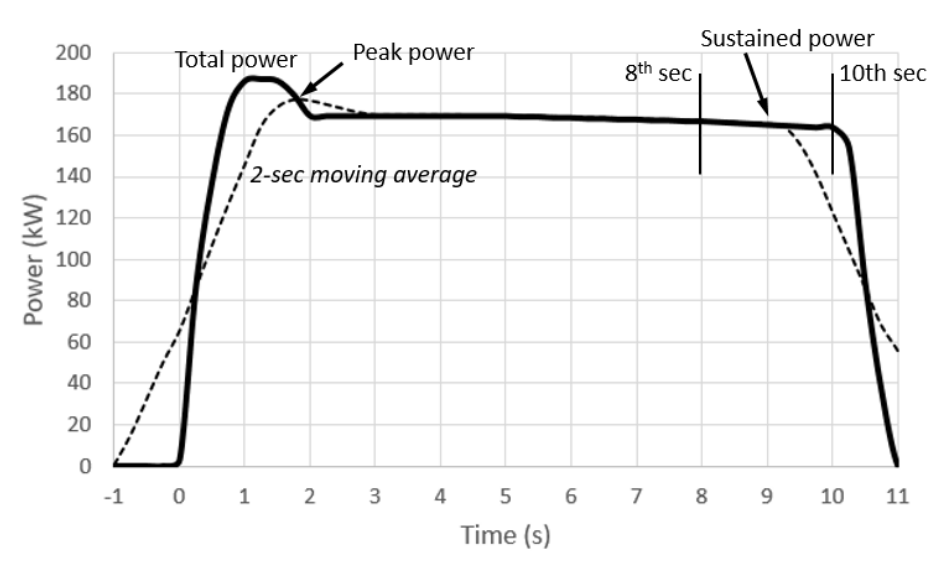 그림 7. 피크 출력(2초 이동평균 최댓값)·지속 출력(8~10초 평균)의 정의 (동일 도식)
4. Application for approval — 승인 신청
4.1
The application shall be submitted by the manufacturer or their authorised representative to the Type Approval Authority.
승인 신청은 제작사 또는 정당하게 위임된 대리인이 형식승인기관에 제출한다.
4.1.1
The application shall be drawn up in accordance with the model of the information document set out in Annex 1.
신청서는 부속서 1의 정보문서 양식에 따라 작성한다.
4.2
An appropriate number of vehicles representative of the vehicle type to be approved shall be submitted to the Technical Service responsible for the approval tests.
승인시험을 담당하는 기술기관에 해당 형식을 대표하는 차량을 적정 대수 제출한다.
4.3
Changes to the make of a system, component or separate technical unit after type-approval shall not automatically invalidate it, unless original characteristics or parameters are changed such that the system power is adversely affected.
형식승인 후 시스템·부품·기술단위의 변경은, 원래 특성·파라미터가 시스템 출력에 악영향을 주도록 바뀌지 않는 한 자동으로 승인을 무효화하지 않는다.
4.4
The Type Approval Authority shall verify the existence of satisfactory provisions to ensure an effective check of conformity of production before approval is granted.
형식승인기관은 승인 전 생산적합성의 효과적 점검을 보장하는 충분한 규정의 존재를 확인한다.
5. Approval — 승인
5.1
If the vehicle type meets all relevant requirements of this Regulation, approval shall be granted and an approval number assigned. The same Contracting Party shall not assign the same number to another vehicle type.
형식이 이 규정의 모든 관련 요건을 충족하면 승인하고 승인번호를 부여한다. 동일 체약국은 같은 번호를 다른 형식에 부여할 수 없다.
5.2
The type-approval number consists of four sections separated by '*': (1) 'E' + distinguishing number of the granting Contracting Party; (2) the Regulation number + 'R' + two digits for the amendment series (00 original) + '/' + two digits for the supplement; (3) a four-digit sequential number (from 0001); (4) a two-digit extension number (from 00). Example: E11*177R01/01*0123*01.
승인번호는 '*'로 구분된 4구획: (1) 'E'+승인 체약국 식별번호; (2) 규정번호+'R'+개정시리즈 2자리(원형 00)+'/'+보충 2자리; (3) 4자리 일련번호(0001부터); (4) 2자리 확장번호(00부터). 예: E11*177R01/01*0123*01.
5.3
Notice of approval, extension or refusal shall be communicated to the Contracting Parties to the 1958 Agreement applying this Regulation by a form conforming to the model in Annex 2.
승인·확장·거부 통보는 부속서 2 양식으로, 이 규정을 적용하는 1958협정 체약국에 전달한다.
6. Markings — 표시
6.1.1
An international approval mark consisting of a circle surrounding the letter 'E' followed by the distinguishing number of the approving country.
'E'를 둘러싼 원과 승인국 식별번호로 구성된 국제 승인마크.
6.1.2
The number of this Regulation, followed by 'R', a dash and the approval number, placed to the right of the circle.
규정번호+'R'+대시+승인번호를 원의 오른쪽에 배치.
6.1.3
~6.5
~6.5
If the vehicle is also approved under other Regulations in the same country, the symbol need not be repeated and the regulation/approval numbers are placed in vertical columns. The mark shall be clearly legible and indelible, placed close to or on the vehicle data plate. Annex 3 gives examples of the arrangement.
같은 국가에서 다른 규정으로도 승인된 경우 기호 반복 불필요, 규정·승인번호를 세로 열로 배치. 마크는 선명·불멸이어야 하며 차량 명판 부근·위에 둔다. 배열 예시는 부속서 3.
7. Test conditions — 시험 조건
7.1.1
Dynamometer: the power absorption capacity in fixed speed control mode shall be sufficient for the maximum power of the vehicle. Due to the short duration of maximum power (~10 s), a short-duration power rating of the dynamometer may apply with approval of the Type-Approval Authority.
동력계: 고정속도 제어 모드의 출력 흡수 용량은 차량 최대출력에 충분해야 한다. 최대출력 지속이 약 10초로 짧아, 기관 승인 시 동력계 단시간 출력 정격 적용 가능.
7.1.2
Test room: temperature set point of 25 °C, actual value within ±5 °C (23 °C at the manufacturer's request). Atmospheric pressure between 80 and 110 kPa. To ensure comparability with ICE power, if reference atmospheric conditions cannot be set, for SI engines 0.93 ≤ X ≤ 1.07 and for CI engines 0.9 ≤ Y ≤ 1.1 (X/Y per ISO 1585:2020, UN R85, or SAE J1349).
시험실: 설정 25°C, 실제값 ±5°C 이내(제작사 요청 시 23°C). 대기압 80~110 kPa. ICE 출력 비교성 확보를 위해 기준 대기조건 미설정 시 SI엔진 0.93≤X≤1.07, CI엔진 0.9≤Y≤1.1(X/Y는 ISO 1585:2020·UN R85·SAE J1349 기준).
7.1.3
Cooling fan: a current of air of variable speed sufficient to maintain proper operating temperatures; above 5 km/h the blower outlet velocity equals the dynamometer speed within ±10%. Excessive cooling is prohibited.
냉각팬: 적정 작동온도 유지에 충분한 가변 풍속; 5 km/h 초과 시 송풍 풍속을 동력계 속도에 ±10% 이내로 일치. 과냉 금지.
7.1.4
Soak area: temperature set point of 25 °C, actual value within ±5 °C (23 °C at the manufacturer's request).
침지구역: 설정 25°C, 실제값 ±5°C 이내(제작사 요청 시 23°C).
7.2.1
Measurement items and accuracy (Table 2), traceable to an approved standard: engine speed ±10 min⁻¹ or ±0.5%; voltage/current ±0.3% FSD or ±1% of reading; intake manifold pressure ±2%; fuel flow rate ±3%; axle torque ±6 Nm or ±0.5%; axle speed ±0.05 s⁻¹ or ±1%; dynamometer speed ±0.2 km/h; force ±10 N; time ±100 ms.
측정 항목·정확도(Table 2, 승인 표준에 소급): 엔진회전수 ±10 min⁻¹ 또는 ±0.5%; 전압·전류 ±0.3%FSD 또는 읽음값 ±1%; 흡기압 ±2%; 연료유량 ±3%; 축토크 ±6Nm 또는 ±0.5%; 축회전수 ±0.05 s⁻¹ 또는 ±1%; 동력계 속도 ±0.2 km/h; 힘 ±10 N; 시간 ±100 ms.
7.2.2
Measurement frequency: all items in Table 2, unless otherwise specified, shall be measured and recorded at ≥10 Hz. Atmospheric pressure and room temperature shall be recorded at least at the start and after the end of vehicle running.
측정 주기: 표 2의 모든 항목은 별도 명시가 없으면 10Hz 이상 측정·기록. 대기압·실온은 최소 운전 시작 시와 종료 후 기록.
8.1 Test procedure — General & required information — 시험 절차: 총칙·필요정보
8.1.1
TP1 is based on measured electrical power, estimated ICE power, and estimated electrical conversion efficiency. TP2 is based on measured torque and speed at the drive shaft(s)/wheel hub(s) and estimated mechanical conversion efficiency. They are intended to be technically equivalent. Each powered axle is tested by chassis or hub dynamometer; two powered axles require a 4WD chassis dynamometer or simultaneous hub dynamometers. Where maximum power exceeds available dynamometers, a system bench (possibly with simulators) may be used.
TP1은 측정 전기출력·산정 ICE 출력·추정 전기변환효율, TP2는 구동축·휠허브 측정 토크·회전수·추정 기계변환효율에 기반하며 기술적으로 등가다. 각 구동축은 섀시 또는 허브 동력계로 시험; 2축 구동은 4WD 섀시 또는 양축 동시 허브 동력계. 최대출력이 가용 동력계를 초과하면 시스템 벤치(시뮬레이터 포함 가능) 사용 가능.
8.1.1.1
Power flow description: the manufacturer shall provide a description sufficient to identify the energy flow paths and conversions during the maximum power condition, from each propulsion energy storage system to each powered axle, indicating each non-propulsion auxiliary and peripheral powered by the REESS (including DC/DC converter and HV auxiliaries), the applicable reference points (Annex 4), the measurement points (TP1 or TP2), and the components to which K factors apply.
동력흐름 기술서: 제작사는 최대출력 조건에서 각 추진 에너지저장장치→각 구동축의 에너지 흐름·변환을 식별하기에 충분한 기술서를 제공한다. REESS가 구동하는 비구동 보조·주변장치(DC/DC·고전압 보조 포함), 적용 기준점(부속서 4), 측정점(TP1/TP2), K계수 적용 부품을 명시한다.
8.1.1.2
Energy conversion factors (K factors): for TP1, provide the electrical conversion efficiency K1 between each electrical measurement point and the corresponding reference point (output of electric machine(s) divided by input power to the inverter). K1 is verified by an applicable standard such as ISO 21782 or SAE J2907. For TP2, provide the mechanical conversion efficiency K2 for each powered axle (output power to the axle/hub divided by input power to the gearbox). K2 is determined by output/input power or other approved methods. Both are subject to verification by the Type-Approval Authority.
에너지 변환계수(K계수): TP1은 각 전기 측정점↔기준점의 전기변환효율 K1(전동기 출력 ÷ 인버터 입력)을 제공하며 ISO 21782·SAE J2907 등으로 검증. TP2는 각 구동축의 기계변환효율 K2(축/허브 출력 ÷ 기어박스 입력)를 제공하며 출력/입력 또는 승인된 방법으로 결정. 둘 다 형식승인기관 검증 대상.
8.1.1.3
Speed of maximum power: shall be determined by the procedure in Annex 5, by the manufacturer or the Type-Approval Authority.
최대출력 속도: 부속서 5 절차에 따라 제작사 또는 형식승인기관이 결정.
8.1.1.4
Other information: the manufacturer shall specify the normal operating range for each operational metric listed in 8.8.1, and for any dynamometer operation mode (see 8.7) shall provide a list of deactivated devices and justification.
기타 정보: 제작사는 8.8.1의 각 운전지표 정상 운전범위를 명시하고, 동력계 운전모드(8.7)에 대해 비활성화 장치 목록과 사유를 제공한다.
8.1.2
Required measurements: the test vehicle shall be instrumented for the necessary inputs. Onboard data for engine speed, intake manifold pressure and fuel flow rate is permissible; onboard data for other measurements is permissible if accuracy/frequency per 7.2 is demonstrated. Measurements common to TP1 and TP2 include accelerator pedal command, atmospheric pressure, room temperature, and operational metrics. For internal validation (8.11), the power delivered to the dynamometer during the maximum power condition shall be recorded at ≥10 Hz.
필요 측정: 시험차량에 필요한 입력값 계측장치를 설치한다. 엔진회전수·흡기압·연료유량은 차재 데이터 허용; 그 외는 7.2의 정확도·주기를 입증하면 차재 데이터 허용. TP1·TP2 공통 측정은 가속페달 지령, 대기압, 실온, 운전지표. 내부검증(8.11)을 위해 최대출력 조건에서 동력계에 전달된 출력을 10Hz 이상 기록.
8.1.2.1
Measurements specific to TP1: current and voltage at the REESS or inverter inputs (per 8.1.3.1), and ICE speed, intake manifold pressure and fuel flow rate (if an ICE contributes propulsion power). TP1 also requires an applicable full-load power curve for the ICE. If a DC/DC converter powers the 12 V bus, current/voltage at its input may be measured in lieu of the 1.0 kW default. If HV auxiliaries other than the DC/DC converter are REESS-powered, their consumption shall be measured or estimated.
TP1 고유 측정: REESS 또는 인버터 입력의 전류·전압(8.1.3.1에 따라), 그리고 ICE가 구동에 기여하면 ICE 회전수·흡기압·연료유량. TP1은 ICE 전부하 출력곡선도 필요. DC/DC가 12V 버스를 구동하면 1.0kW 기본값 대신 그 입력 전류·전압을 측정 가능. DC/DC 외 고전압 보조가 REESS 구동 시 소비전력을 측정·추정.
8.1.2.2
Measurements specific to TP2: torque and rotational speed at the powered axle shafts or wheel hubs. If ICE power needs correction (8.9.3.2), TP1 current/voltage measurements may also apply. Wheel torque/speed may be provided by a hub dynamometer or calibrated devices. If a powered axle delivers power through a differential, instrumenting only one drive shaft/hub is sufficient and the measured torque is multiplied by 2.
TP2 고유 측정: 구동축·휠허브의 토크·회전수. ICE 출력 보정(8.9.3.2)이 필요하면 TP1 전류·전압 측정도 적용 가능. 휠 토크·회전수는 허브 동력계 또는 교정된 장치로 제공. 구동축이 차동기어로 동력을 전달하면 한쪽 축/허브만 계측하고 측정 토크에 2를 곱한다.
8.1.3 Test procedure applicability — 시험절차 적용성
8.1.3
Applicability of TP1 and TP2 varies with powertrain architecture. The Type-Approval Authority shall confirm that the reference points in the power flow description accord with Annex 4 and the 3.5.3 definition. Where both are applicable, the manufacturer may choose. The reported rating shall be identified as determined by TP1 or TP2.
TP1·TP2의 적용성은 파워트레인 구조에 따라 다르다. 형식승인기관은 동력흐름 기술서의 기준점이 부속서 4 및 3.5.3 정의에 부합하는지 확인한다. 둘 다 가능하면 제작사가 선택. 보고된 정격은 TP1·TP2 중 무엇으로 결정됐는지 명시한다.
8.1.3.1
Applicability of TP1 requires that the power passing through all reference points can be accurately determined. TP1 is typically applicable if 8.1.3.1.1 or 8.1.3.1.2 is fulfilled.
TP1 적용성은 모든 기준점 출력을 정확히 결정할 수 있어야 한다. 8.1.3.1.1 또는 8.1.3.1.2 충족 시 통상 적용 가능.
8.1.3
.1.1
.1.1
The power flow description indicates that current from each REESS powers a single electric machine, current and voltage at each REESS output can be determined, and an accurate K1 is provided. (Figure 16) Power at R [kW] = (U × I / 1000) × K1.
각 REESS 전류가 단일 전동기를 구동하고, 각 REESS 출력의 전류·전압을 결정할 수 있으며, 정확한 K1이 제공됨. (그림 16) R 출력 [kW] = (U × I / 1000) × K1.
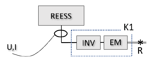 그림 16. 사례 8.1.3.1.1. — TP1 적용 (동일 도식)
8.1.3
.1.2
.1.2
Or at least one of (a)–(d): (a) current/voltage at each inverter input with accurate K1(n) per reference point (Figure 17); (b) current/voltage at REESS output with combined K1comb (Figure 18); (c) REESS output with identical conversion efficiency, same K1 (Figure 19); (d) REESS output with distribution ratios DR(1), DR(2) from onboard torque commands (Figure 19a).
또는 (a)~(d) 중 하나 이상: (a) 각 인버터 입력 전류·전압 + 기준점별 정확한 K1(n)(그림 17); (b) REESS 출력 전류·전압 + 통합 K1comb(그림 18); (c) REESS 출력 + 동일 변환효율, 단일 K1(그림 19); (d) REESS 출력 + 차재 토크지령 기반 분배율 DR(1)·DR(2)(그림 19a).
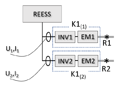 그림 17. 사례 8.1.3.1.2.(a) — 인버터별 K1(n) (동일 도식)
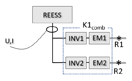 그림 18. 사례 8.1.3.1.2.(b) — 통합 K1comb (동일 도식)
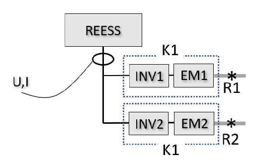 그림 19. 사례 8.1.3.1.2.(c) — 동일 K1 (동일 도식)
8.1.3.2
Applicability of TP2 requires that the power through all reference points can be accurately determined; each powered axle is evaluated separately, and TP2 applies only if applicable to all powered axles. TP2 is typically applicable to an axle if 8.1.3.2.1 or 8.1.3.2.2 is fulfilled.
TP2 적용성은 모든 기준점 출력을 정확히 결정할 수 있어야 하며, 구동축마다 별도 평가하고 모든 구동축에 적용 가능할 때만 사용. 8.1.3.2.1 또는 8.1.3.2.2 충족 시 통상 적용 가능.
8.1.3
.2.1
.2.1
Torque to the axle originates from a single reference point routed only to that axle, with an accurate K2. (Figure 20) Power at R1 [kW] = (2π × τ × rps / 1000) / K2.
축 토크가 단일 기준점에서 나와 그 축으로만 전달되고 정확한 K2가 있음. (그림 20) R1 출력 [kW] = (2π × τ × rps / 1000) / K2.
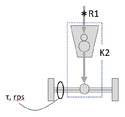 그림 20. 사례 8.1.3.2.1. — TP2 적용 (동일 도식)
8.1.3
.2.2
.2.2
Or the axle torque is a combined torque from a set of reference points routed via the same mechanical path with an accurate combined K2. (Figure 21) Power at (R1+R2) = (2π × τ × rps / 1000) / K2. TP2 is not applicable if R1, R2, or (R1+R2) cannot be resolved from the available measurement (Figure 22).
또는 축 토크가 같은 기계 경로로 합쳐진 기준점 집합의 토크이고 정확한 통합 K2가 있음. (그림 21) (R1+R2) 출력 = (2π × τ × rps / 1000) / K2. 가용 측정으로 R1·R2·(R1+R2)를 분해할 수 없으면 TP2 적용 불가(그림 22).
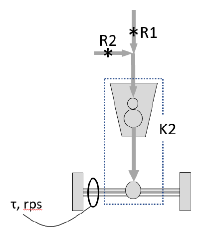 그림 21. 사례 8.1.3.2.2. — 통합 K2로 (R1+R2) (동일 도식)
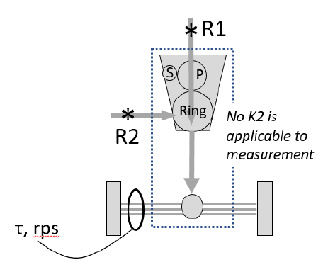 그림 22. TP2 적용 불가 — 가용 측정으로 R1·R2 분해 불가 (동일 도식)
8.2–8.7 Preparation — 준비(동력계·차량·계측·충전·침지·설치)
8.2.1
Roller (chassis dynamometer only): the roller(s) shall be clean, dry and free from foreign material that can cause tyre slippage.
롤러(섀시 동력계만): 롤러는 청결·건조하고 타이어 슬립을 유발하는 이물질이 없어야 한다.
8.2.2
Tyre slippage (chassis dynamometer only): measures shall be taken to stabilise tyre slippage during maximum power; any additional weight or other measures shall be recorded.
타이어 슬립(섀시 동력계만): 최대출력 중 슬립을 안정화하는 조치를 취하고, 추가 중량 등 조치를 기록한다.
8.2.3
Dynamometer warm-up: warm up per the manufacturer's recommendation so the frictional losses stabilise.
동력계 워밍업: 마찰 손실이 안정되도록 제조사 권고에 따라 예열한다.
8.2.4
Dynamometer control: for vehicle conditioning (8.8.3) the dynamometer is in road load mode; for the power test (8.8.6) it is in fixed speed mode.
동력계 제어: 차량 컨디셔닝(8.8.3)은 도로부하 모드, 출력시험(8.8.6)은 고정속도 모드.
8.3
Preparation of vehicle: presented in good condition and run-in per the manufacturer. OVC-/NOVC-HEVs shall be run-in 3,000–15,000 km; PEVs at least 300 km or one full charge distance. On a chassis dynamometer, original-equipment tyres inflated to the recommended pressure (which may be increased up to 50% to prevent slippage); the same pressure is used throughout and recorded. Manufacturer-specified lubricants and the ICE certification fuel shall be used.
차량 준비: 양호한 상태로 제조사 권고에 따라 길들이기. OVC-/NOVC-HEV는 3,000~15,000km, PEV는 최소 300km 또는 1회 완충거리 중 긴 쪽 길들이기. 섀시 동력계에서는 순정 타이어를 권장 공기압(슬립 방지를 위해 최대 50%까지 증가 가능)으로; 동일 압력을 전 시험에 사용·기록. 제조사 지정 윤활유와 ICE 인증 연료를 사용.
8.4
Preparation of measurement devices: the measurement devices shall be installed at suitable position(s) within the vehicle.
계측장치 준비: 측정장치를 차량 내 적절한 위치에 설치한다.
8.5
Initial charge of REESS: for PEVs and OVC-HEVs, prior to or during soak, charge the REESS to an initial SOC at which maximum system power is obtained (the manufacturer may specify it). The initial charge is conducted at an ambient temperature of 20 ± 10 °C, per the manufacturer's normal-operation procedure; the SOC is confirmed by a manufacturer-provided method.
REESS 초기충전: PEV·OVC-HEV는 침지 전·중에 최대 시스템 출력이 얻어지는 초기 SOC로 충전(제작사가 명시 가능). 초기충전은 주위온도 20±10°C에서 제조사 정상운전 절차로 수행하고, SOC는 제조사 제공 방법으로 확인.
8.6
Vehicle soak: soak in the soak area for a minimum of 6 hours and a maximum of 36 hours (engine cover opened or closed). The manufacturer may recommend a specific time within 6–36 h to stabilise the high-voltage battery temperature. Soak conditions per 7.1.4.
차량 침지: 침지구역에서 최소 6시간~최대 36시간 침지(엔진커버 개폐 무관). 고전압 배터리 온도 안정화를 위해 제작사가 6~36h 내 특정 시간을 권고 가능. 침지조건은 7.1.4.
8.7
Vehicle installation: install on the dynamometer per the dynamometer manufacturer's recommendation or regional/national regulations. Auxiliary devices shall be switched off/deactivated unless required by regional legislation. A dynamometer operation mode may be activated per the manufacturer's instruction; the list of deactivated devices and justification shall be provided and the mode approved by the Authority and recorded. The mode shall not alter any part affecting emissions, fuel/energy consumption, or maximum power. Onboard measurement devices shall be warmed up appropriately.
차량 설치: 동력계 제조사 권고 또는 지역/국가 규정에 따라 설치. 보조장치는 지역 법규가 요구하지 않는 한 끄거나 비활성화. 제조사 지시로 동력계 운전모드를 활성화할 수 있으며, 비활성화 장치 목록·사유를 제공하고 기관 승인·기록. 운전모드는 배출·연료/에너지 소비·최대출력에 영향을 주는 부품을 변경해선 안 됨. 차내 측정장치는 적절히 예열.
8.8 Test sequence — 시험 순서
8.8.1
General: the test is carried out per 8.8.3–8.8.8 and 8.9–8.11 (Figure 23), stopped immediately if a powertrain warning indicator turns on. The following operational metrics, if present, are monitored and recorded throughout: (a) engine coolant temperature, (b) battery temperature, (c) transmission/gearbox oil temperature, (d) battery SOC, (e) electric machine temperature. The manufacturer specifies the normal operating range for each.
총칙: 시험은 8.8.3~8.8.8 및 8.9~8.11(그림 23)에 따라 수행하고, 파워트레인 경고등 점등 시 즉시 중단. 다음 운전지표(있으면)를 전 과정 모니터·기록: (a) 엔진 냉각수온, (b) 배터리 온도, (c) 변속기/기어박스 유온, (d) 배터리 SOC, (e) 전동기 온도. 각 정상범위는 제작사가 명시.
8.8.2
Speed of maximum power: if not provided by the manufacturer, or if the Authority wishes to verify it, determine it by the procedure in Annex 5.
최대출력 속도: 제작사가 제공하지 않거나 기관이 검증하려면 부속서 5 절차로 결정.
8.8.3
Vehicle conditioning: start data collection; operate the vehicle until the manufacturer-specified normal operating temperature ranges are reached and stabilised. Initial conditioning: in power-rating mode at 60 km/h at the vehicle road load for at least 20 minutes (or as recommended). Record the operational metrics at the end; re-condition during the test as needed.
차량 컨디셔닝: 데이터 수집 시작; 제작사 지정 정상 작동온도 범위에 도달·안정될 때까지 운전. 초기 컨디셔닝: 출력평가 모드, 도로부하 60km/h로 최소 20분(또는 권고대로). 종료 시 운전지표 기록; 시험 중 필요시 재컨디셔닝.
8.8.4
REESS adjustment: monitor SOC during conditioning and adjust at the end to the SOC at which maximum system power is obtained (as recommended). Adjustment may use light regenerative braking or coasting in fixed speed mode; the charge rate is monitored and limited to avoid battery overheating or de-rating.
REESS 조정: 컨디셔닝 중 SOC를 모니터하고 종료 시 최대 시스템 출력이 얻어지는 SOC로 조정. 경회생제동 또는 고정속도 타행으로 가능; 충전율은 배터리 과열·디레이팅 방지를 위해 모니터·제한.
8.8.5
Vehicle operation: for vehicles with driver-selectable modes, select and record the mode for which a rating is desired (power-rating mode). Place the dynamometer in fixed speed mode and set it to the speed of maximum power; allow it to stabilise.
차량 운전: 운전자 선택 모드가 있으면 정격을 구하려는 모드(출력평가 모드)를 선택·기록. 동력계를 고정속도 모드로 두고 최대출력 속도로 설정 후 안정화.
8.8.6
Power test: give the maximum accelerator pedal command (by pedal position or vehicle network) for at least 10 s, as rapidly as possible. If needed, vary the command beforehand as recommended (e.g. kickdown). With driver-selectable gears, select the gear recommended for a typical driver to achieve maximum power; special non-typical modes are not permitted.
출력시험: 최대 가속페달 지령(페달 위치 또는 차량 네트워크)을 최소 10초간 가능한 빠르게. 필요시 사전에 권고대로 지령을 조절(예: 킥다운). 운전자 선택 기어는 일반 운전자가 최대출력을 내도록 권고된 기어 선택; 비일반 특수모드 불가.
8.8.7
Repetition of power test: repeat for a total of five repetitions (Figure 23); before the 2nd and subsequent repetitions, adjust the REESS per 8.8.4. Monitor temperature-related metrics during all repetitions and re-condition between repetitions if necessary.
출력시험 반복: 총 5회 반복(그림 23); 2회차 이후 매번 8.8.4에 따라 REESS 조정. 전 반복에서 온도 지표를 모니터하고 필요시 반복 사이 재컨디셔닝.
8.8.8
End of vehicle running: record the operational metrics; then stop the vehicle and measurement devices.
차량 주행 종료: 운전지표를 기록한 뒤 차량과 측정장치를 정지.
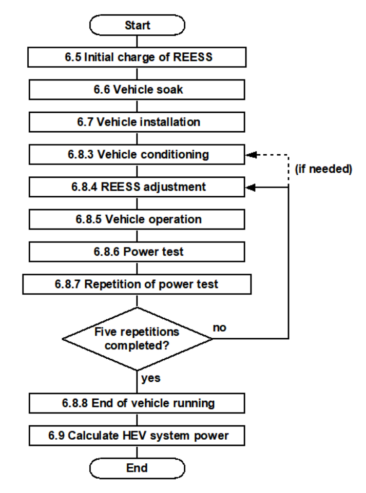 그림 23. 시험 순서 — 초기충전→침지→설치→컨디셔닝→REESS조정→출력시험(5회)→산출 (동일 도식)
8.9–8.11 Calculation & validation — 산출·해석·내부검증
8.9.1
General: for the 2nd–5th repetitions, analyse the time series to compute peak (3.5.9) and sustained (3.5.10) power. The 10-second window begins when the accelerator command reaches maximum and the gear ratio has been constant for at least 10 s. The rating is the mean of the four repetitions; the variation of each is recorded and should be within ±5% of the mean; if too large, check settings and repeat; if not reducible, the rating is subject to Authority approval.
총칙: 2~5회차 시계열로 피크(3.5.9)·지속(3.5.10) 출력을 계산. 10초 구간은 가속지령이 최대에 도달하고 기어비가 최소 10초간 일정할 때 시작. 정격은 4회 평균; 각 회 편차를 기록하고 평균의 ±5% 이내여야 하며, 과대 시 설정 점검·재시험, 줄지 않으면 기관 승인 대상.
8.9.2.1
TP1 — ICE reference point: determine ICE power from the full-load power curve as a function of engine speed (the curve derived from the applicable engine standard — ISO 1585:2020, UN R85, or SAE J1349 — measured steady-state). If |measured fuel flow − certification| < 5% and |gauge pressure − certification| < 5% of the certification intake manifold pressure, use the curve value at the measured engine speed; otherwise re-test under the observed conditions. Linear interpolation may be used between measured speeds.
TP1 — ICE 기준점: ICE 출력을 엔진회전수 함수의 전부하 출력곡선에서 결정(곡선은 적용 엔진표준 ISO 1585:2020·UN R85·SAE J1349의 정상상태 측정). 측정 연료유량·게이지압이 인증값과 각각 5%·(인증 흡기압의)5% 이내면 측정 회전수의 곡선값 사용; 초과 시 관측조건으로 재시험. 측정 회전수 사이는 선형보간 가능.
8.9.2.2
TP1 — electric machine, REESS output measurement: Ri [kW] = (U_REESS × I_REESS / 1000 − P_DCDC − P_aux) × K1, where P_DCDC is the 12 V DC/DC converter power (1.0 kW or measured) and P_aux the power to REESS-powered HV auxiliaries other than P_DCDC (measured or estimated; estimate subject to Authority approval). System power = Σ Ri.
TP1 — 전동기, REESS 출력단 측정: Ri [kW] = (U_REESS × I_REESS / 1000 − P_DCDC − P_aux) × K1. P_DCDC는 12V DC/DC 전력(1.0kW 또는 측정), P_aux는 DC/DC 외 REESS 구동 고전압 보조 전력(측정·추정; 추정은 기관 승인). 시스템 출력 = Σ Ri.
8.9.2.3
TP1 — electric machine, inverter input measurement: Ri [kW] = (U_input × I_input / 1000) × K1.
TP1 — 전동기, 인버터 입력단 측정: Ri [kW] = (U_input × I_input / 1000) × K1.
8.9.3.1
TP2 — calculation: system power = Σ Ri, where Ri = P_axle / K2 and P_axle [kW] = (2π × axle speed[rev·s⁻¹] × axle torque[Nm]) / 1000.
TP2 — 계산: 시스템 출력 = Σ Ri, Ri = P_axle / K2, P_axle [kW] = (2π × 축회전수[rev·s⁻¹] × 축토크[Nm]) / 1000.
8.9.3.2
TP2 — ICE power correction: the ICE power portion shall be corrected per ISO 1585:2020 §6 (or the equivalent of the applicable standard) if the reference atmospheric/temperature or automatic-control conditions cannot be fulfilled.
TP2 — ICE 출력 보정: 기준 대기·온도 또는 자동제어 조건을 충족 못하면 ISO 1585:2020 §6(또는 적용표준의 동등 조항)에 따라 ICE 출력분을 보정.
8.9.3.3
TP2 — corrected rating: where TP2 does not yield a distinct P_ICE (e.g. power-split, Figure 24): (a) identify the summed reference-point set including the ICE point; (b) perform TP1 to determine the non-ICE portion; (c) P_ICE = P_summed − P_summed,non-ICE; (d) correct P_ICE per ISO 1585:2020 §6; (e) corrected system power = Σ(non-ICE reference points) + P_ICE,corrected.
TP2 — 보정 정격: TP2가 별개의 P_ICE를 주지 못하면(예: 동력분기, 그림 24): (a) ICE 기준점을 포함한 합산 기준점 집합 식별; (b) TP1으로 비ICE분 결정; (c) P_ICE = P_summed − P_summed,비ICE; (d) ISO 1585:2020 §6로 P_ICE 보정; (e) 보정 시스템 출력 = Σ(비ICE 기준점) + 보정 P_ICE.
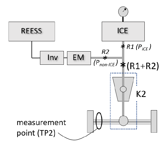 그림 24. TP2가 ICE 출력(R1)의 별개 값을 제공하지 않는 파워트레인 예시 (동일 도식)
8.10
Interpretation of results: the manufacturer's stated peak/sustained system power is accepted if it does not differ by more than ±5% from the value measured by the Technical Service. The parameters/conditions at which peak or sustained power is reached are referenced in Annex 1 Appendix 1.
결과 해석: 제작사 제시 피크/지속 출력은 기술기관 측정값과 ±5% 이내면 인정. 피크·지속 출력 도달 시의 파라미터·조건은 부속서 1 Appendix 1에 기재.
8.11
Internal validation: the implied downstream efficiency between the reference point(s) and the road shall not exceed 1, computed as the dynamometer 8–10 s average power divided by the sustained system power (before any 8.9.3.3 correction).
내부 검증: 기준점↔노면 간 함의 하류효율은 1을 넘지 않아야 하며, 동력계 8~10초 평균출력 ÷ (보정 전) 지속 시스템 출력으로 계산.
9. Families within Types — 형식 내 패밀리
9.1
Only vehicles that are the same with respect to all of the following elements may be part of the same vehicle type: (a) powertrain system configuration, including number, type and mechanical arrangement of power sources and operating strategy; (b) ICE power rating; (c) net power and construction type (e.g. asynchronous, synchronous) of all electric machines and the type of electric energy converter(s) between the electric machine(s) and the battery; (d) type of battery cell (format, capacity, voltage, chemistry); (e) type of battery pack (configuration: number of cells in series and mode of connection); (f) nominal voltage of the battery; (g) maximum current of the battery; (h) type of vehicle (PEV, OVC-HEV, or NOVC-HEV). At the manufacturer's request, with Authority approval and appropriate technical justification, deviation from the above criteria is allowed.
다음 요소가 모두 동일한 차량만 같은 형식에 속할 수 있다: (a) 동력원의 수·종류·기계적 배치와 운영전략을 포함한 파워트레인 구성; (b) ICE 출력정격; (c) 모든 전동기의 순출력·구조형식(비동기/동기 등) 및 전동기–배터리 간 전력변환기 형식; (d) 배터리 셀 형식(규격·용량·전압·화학); (e) 배터리 팩 형식(직렬 셀 수·연결 방식); (f) 배터리 공칭전압; (g) 배터리 최대전류; (h) 차량 유형(PEV·OVC-HEV·NOVC-HEV). 제작사 요청·기관 승인·적절한 기술적 정당화가 있으면 위 기준에서 벗어날 수 있다.
9.2
Within a vehicle type, vehicles having the same characteristics with respect to their evaluation for system power may be grouped into vehicle families.
한 차량 형식 내에서, 시스템 출력 평가 측면의 특성이 동일한 차량은 차량 패밀리로 묶을 수 있다.
9.3
Identification of families for type-approval: to differentiate between different families within the same vehicle type (e.g. when different K-factors do not affect the parameters in paragraph 9.1), the manufacturer may specify a unique identifier of the format SP-nnnnnnnnnnnnnnn-WMI, where nnnnnnnnnnnnnnn is up to fifteen characters (0-9, A-Z, '_') and WMI is the world manufacturer identifier per ISO 3780:2009. The WMI owner ensures the combination is unique to the family.
형식승인용 패밀리 식별: 같은 형식 내 서로 다른 패밀리를 구분하기 위해(예: K계수가 달라도 9.1 파라미터에 영향이 없는 경우) 제작사는 SP-nnnnnnnnnnnnnnn-WMI 형식의 고유 식별자를 지정할 수 있다. nnnnnnnnnnnnnnn은 최대 15자(0-9, A-Z, '_'), WMI는 ISO 3780:2009의 세계제작사식별코드. WMI 소유자가 그 조합이 패밀리에 고유하도록 보장한다.
10. Modification and extension of the type approval — 형식승인의 변경·확장
10.1
Every modification of the vehicle type shall be notified to the Type Approval Authority that approved the vehicle type. The Authority may then either (10.1.1) or (10.1.2):
형식의 모든 변경은 그 형식을 승인한 형식승인기관에 통지한다. 기관은 (10.1.1) 또는 (10.1.2) 중 하나를 택할 수 있다:
10.1.1
Consider that the modifications are contained within the families covered by the approval or are unlikely to have an appreciable adverse effect on the Type Approval values, in which case the original approval remains valid for the modified vehicle type; or
변경이 승인 대상 패밀리 내에 있거나 형식승인 값에 뚜렷한 악영향을 줄 가능성이 낮다고 보아, 이 경우 기존 승인이 변경된 형식에도 유효하다고 간주; 또는
10.1.2
Require a further test report from the Technical Service responsible for conducting the tests.
시험을 담당하는 기술기관에 추가 시험보고를 요구.
10.2
Confirmation or refusal of approval, specifying the alterations, shall be communicated by the procedure specified in paragraph 5.3 to the Contracting Parties to the Agreement which apply this Regulation.
변경 사항을 명시한 승인의 확인 또는 거부는, 5.3에 규정된 절차로 이 규정을 적용하는 협정 체약국에 통보한다.
10.3
The Type Approval Authority issuing the extension of approval shall assign a series number to the extension and inform the other Contracting Parties to the 1958 Agreement applying this Regulation by means of a communication form conforming to the model in Annex 2.
승인 확장을 발급하는 형식승인기관은 그 확장에 일련번호를 부여하고, 부속서 2 양식의 통보서로 이 규정을 적용하는 다른 1958협정 체약국에 통지한다.
10.4
Extension of an approval: an existing type approval may be extended, e.g. by adding new vehicle families. The added families must also fulfil the requirements of paragraph 9.1. This may require further verification by the Type Approval Authority (e.g. when different K-factors apply).
승인의 확장: 기존 형식승인은 예컨대 새 차량 패밀리를 추가하여 확장할 수 있다. 추가 패밀리도 9.1 요건을 충족해야 한다. 이는 형식승인기관의 추가 검증을 요할 수 있다(예: K계수가 다른 경우).
11–15. CoP · Penalties · Discontinuation · Introductory · Authorities — 생산적합성·벌칙·중단·경과·기관
11
Conformity of production: requirements for power determination of propulsion energy converters are covered by UN Regulation No. 85 §6; compliance with R85 CoP for all converters is considered sufficient. Absent R85 approvals, the manufacturer shall demonstrate compliance with R85 CoP.
생산적합성: 추진 에너지변환기 출력 결정 요건은 UN R85 §6로 포괄되며, 모든 변환기의 R85 생산적합성 준수로 충분한 것으로 본다. R85 승인이 없으면 제작사가 R85 생산적합성 준수를 입증.
12·13
Penalties: approval may be withdrawn for non-conformity; withdrawal is notified to other Contracting Parties via Annex 2. Production definitively discontinued: the approval holder informs the Authority, which notifies other Parties via Annex 2.
벌칙: 미준수 시 승인 철회 가능; 철회는 부속서 2로 타 체약국에 통지. 생산 완전 중단: 승인 보유자가 기관에 통지하고 기관은 부속서 2로 타 체약국에 통보.
14·15
Introductory provisions: from the date of entry into force, Contracting Parties applying this Regulation and also UN R85 may refuse R85-based approvals for in-scope vehicles not also approved to this Regulation. Authorities: Parties communicate to the UN Secretariat the names and addresses of the Technical Services and Type Approval Authorities.
도입 경과규정: 발효일부터, 이 규정과 UN R85를 함께 적용하는 체약국은 본 규정으로도 승인되지 않은 적용범위 차량의 R85 기반 승인을 거부할 수 있다. 기관: 체약국은 기술기관·형식승인기관의 명칭·주소를 UN 사무국에 통보.
Annex 1–3 — 부속서 1~3 (정보문서·통보·승인마크)
An.1
~3
~3
Annex 1: Engine and vehicle characteristics and information document (with an Appendix for the test report; drawings to appropriate scale in A4). Annex 2: Communication form (approval/extension/refusal/withdrawal). Annex 3: Arrangements of the approval mark.
부속서 1: 엔진·차량 제원 및 시험 정보문서(시험성적서 Appendix 포함; 도면은 A4·적정 축척). 부속서 2: 통보 양식(승인·확장·거부·철회). 부속서 3: 승인마크 배열.
Annex 4. Identification of reference points — 부속서 4. 기준점 식별
An.4
1
1
Both TP1 and TP2 transform a set of measurements into a system power rating referenced to one or more reference points. The reference point is the point in the electrified powertrain closest to the engine output shaft of a conventional vehicle, defined in 3.5.3 as where the mechanical energy driving the wheels is first produced. For complex powertrains the reference points may depend on the operating mode or the rating sought.
TP1·TP2 모두 측정값을 하나 이상의 기준점을 기준으로 한 시스템 출력 정격으로 변환한다. 기준점은 전동화 파워트레인에서 종래 차량의 엔진 출력축에 가장 가까운 지점으로, 3.5.3에 바퀴 구동 기계에너지가 처음 생성되는 지점으로 정의. 복잡한 구조에서는 운전 모드·구하려는 정격에 따라 달라질 수 있다.
An.4
2.2
2.2
Parallel architecture (Figure 25): reference points are generally (a) R1 at the engine and (b) R2 at the electric machine, which drives the engine output shaft directly. Both TP1 and TP2 are applicable.
병렬 구조(그림 25): 기준점은 일반적으로 (a) 엔진의 R1, (b) 엔진 출력축을 직접 구동하는 전동기의 R2. TP1·TP2 모두 적용 가능.
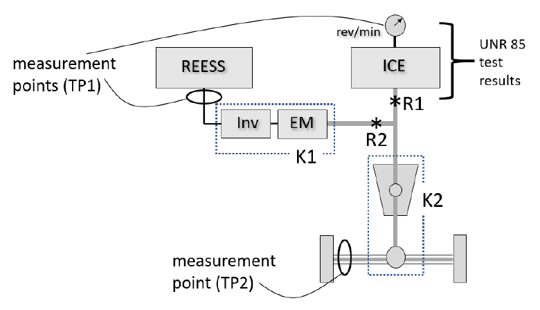 그림 25. 단순 병렬 구조의 기준점 R1·R2 (동일 도식)
An.4
2.3
2.3
Power-split architecture (Figure 26) often uses planetary gear sets; reference points R1 and R2REESS. TP1 determines R1 from engine speed/manifold pressure/fuel flow (full-load curve) and R2REESS from the REESS measurement with K1; TP2 is not applicable.
동력분기 구조(그림 26)는 흔히 유성기어를 쓰며 기준점 R1·R2REESS. TP1은 R1을 엔진 회전수·흡기압·연료량(전부하 곡선)으로, R2REESS를 REESS 측정·K1으로 결정; TP2는 적용 불가.
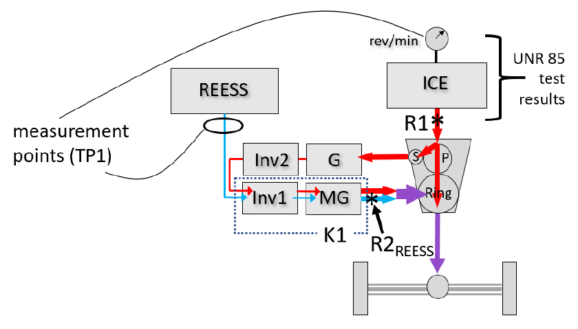 그림 26. 단순 동력분기 구조의 기준점 R1·R2REESS (동일 도식)
An.4
2.4
2.4
Pure series architecture (Figure 27) has no mechanical engine-to-road connection; reference points R1 and R2REESS. TP1 is performed as for the power-split case; TP2 is not applicable.
순수 직렬 구조(그림 27)는 엔진–노면 간 기계적 연결이 없고 기준점 R1·R2REESS. TP1은 동력분기와 동일하게 수행; TP2는 적용 불가.
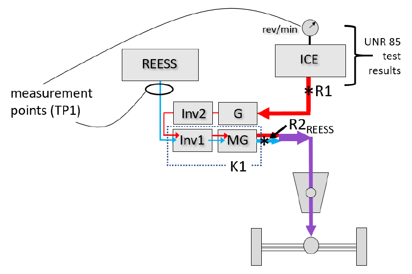 그림 27. 순수 직렬 구조의 기준점 예시 (동일 도식)
An.4
2.5·2.6
2.5·2.6
Where two or more axles drive the vehicle under the maximum power condition, both axles are tested simultaneously; TP1 determines R1 from engine measurements and the electric-machine reference points from inverter inputs with K1 factors. For other architectures not listed, the reference points and applicability are determined by the manufacturer and the responsible authority.
둘 이상의 차축이 최대출력 조건에서 구동하면 양 차축을 동시에 시험; TP1은 R1을 엔진 측정으로, 전동기 기준점을 인버터 입력·K1으로 결정. 열거되지 않은 구조는 제작사와 담당 기관이 기준점·적용성을 결정.
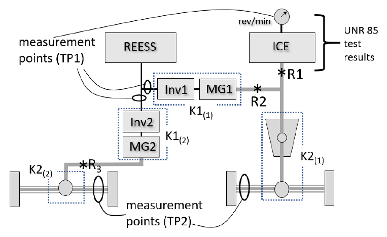 그림 28. 서로 다른 기준점을 통해 출력을 받는 둘 이상의 구동축 구조 (동일 도식)
Annex 5. Speed of maximum power — 부속서 5. 최대출력 속도 결정
An.5
The speed of maximum power (3.5.5) is the speed at the maximum of the power-speed relationship (Figure 29). It is determined by the manufacturer or the Authority by operating the vehicle at a series of fixed dynamometer speeds spaced closely enough to identify it with sufficient confidence; at each operating point the power is taken from dynamometer data or from torque × speed. The result is reported as an integer in km/h. Where the manufacturer has specified it and verification is desired, test at points above and below the specified speed (Figure 30).
최대출력 속도(3.5.5)는 출력-속도 관계의 정점에서의 속도(그림 29). 제작사 또는 기관이 충분히 촘촘한 일련의 고정 동력계 속도로 차량을 운전해 결정하며, 각 운전점 출력은 동력계 데이터 또는 토크×회전수로 구한다. 결과는 km/h 정수로 보고. 제작사가 명시하고 검증이 필요하면 명시 속도 위·아래 지점을 시험(그림 30).
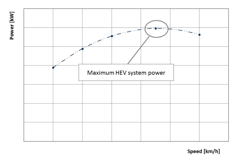 그림 29. 출력-속도 관계 — 최대 시스템 출력 지점 (동일 도식)
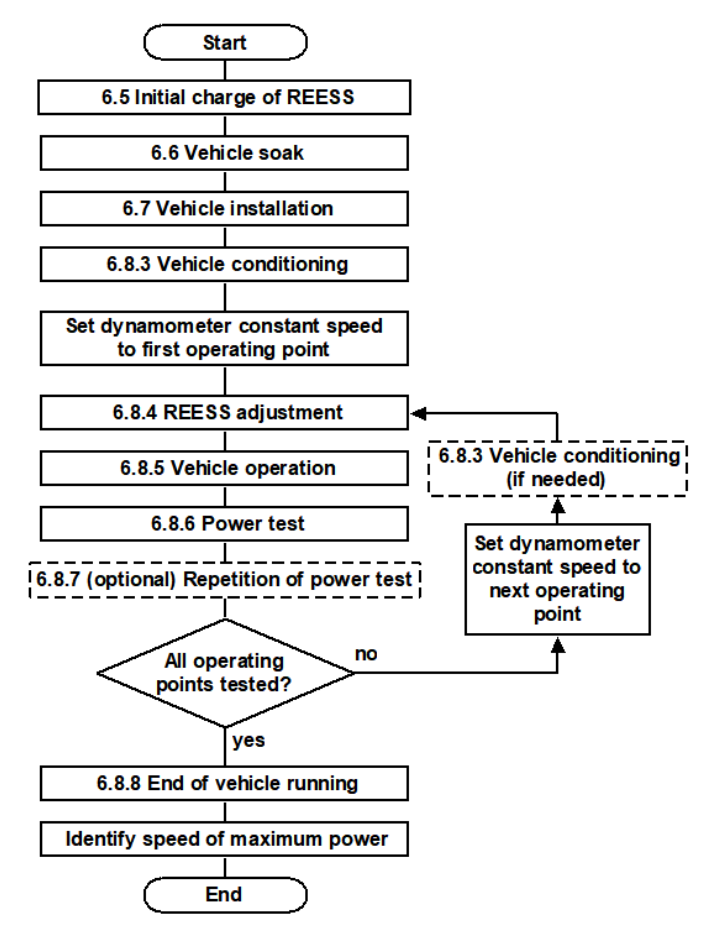 그림 30. 최대출력 속도 결정을 위한 시험 순서 (동일 도식)